
Focus ZTS L4-2.0L DOHC VIN 3 (2001)
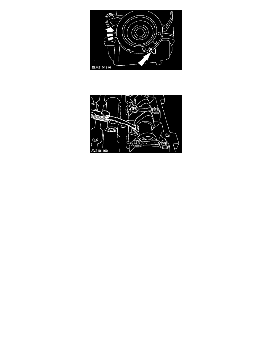
3. CAUTION: Only rotate the engine on the crankshaft and in its rotation direction.
Set the engine to TDC on cylinder number 1.
4. NOTE: Note down each cylinder number and the valve clearances measured.
Measure the valve clearance using feeler gauges.
^
Permitted valve clearance: inlet (0.11-0.18 mm)
^
Permitted valve clearance: exhaust (0.27-0.34 mm)
5. CAUTION: Only rotate the engine on the crankshaft.
Measure the valve clearance (continued).
^
Rotate the engine a further 180 degrees on the crankshaft in its rotation direction. In this instance, the measuring sequence follows the firing
order 1-3-4-2.
^
Repeat the previous steps for the other cylinders.
6. NOTE:
^
Only carry out the following steps when the valve clearance must be adjusted.
^
Aim to set the valve clearances to the middle of the range (inlet 0.15 mm; exhaust 0.30 mm)
Remove the camshafts.
7. NOTE: The number on the tappet indicates the tappet thickness.
Determine the tappet thickness required.
^
Remove the adjusting tappet and read the thickness from the back side.
^
Determine the tappet thickness required and insert the correct tappet.
^
Inlet valves: tappet thickness required = thickness of currently installed tappet + measured valve clearance-0.15 mm.
^
Exhaust valves: tappet thickness required = thickness of currently installed tappet + measured valve clearance-0.30 mm.
8. CAUTION: Set the piston on cylinder number 1 to approximately 25 mm before TDC.
Install the camshafts and camshaft timing belts.
9. NOTE:
^
Turn the camshaft to measure the valve clearance
^
Do not attach the timing belt until the setting is in order.
Recheck the valve clearance after adjustment is complete.