
Focus ZTS L4-2.0L DOHC VIN 3 (2001)
3. Tighten the bolts in the sequence shown.
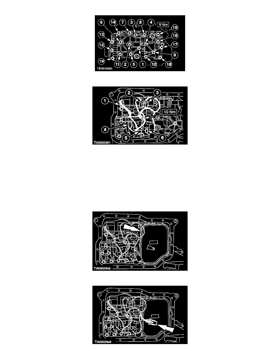
4. NOTE: It is necessary to connect the connectors in the same positions as noted in disassembly. Connector color letters are casted into the
solenoid body.
Install the main control wire harness, connect the electrical connectors and tighten the ground bolt.
Install the main control valve body.
1. Solenoid SSC; Color N (Neutral/White)
2. Solenoid SSE; Color G (Green)
3. Solenoid SSD; Color L (Blue)
4. Solenoid EPC; Color B (Black)
5. Solenoid SSA; Color N (Neutral)
6. Solenoid SSB; Color B (Black)
5. Install the fluid filter.