
Focus ZX5 L4-2.0L DOHC VIN 3 (2002)
Variable Valve Timing Actuator: Description and Operation
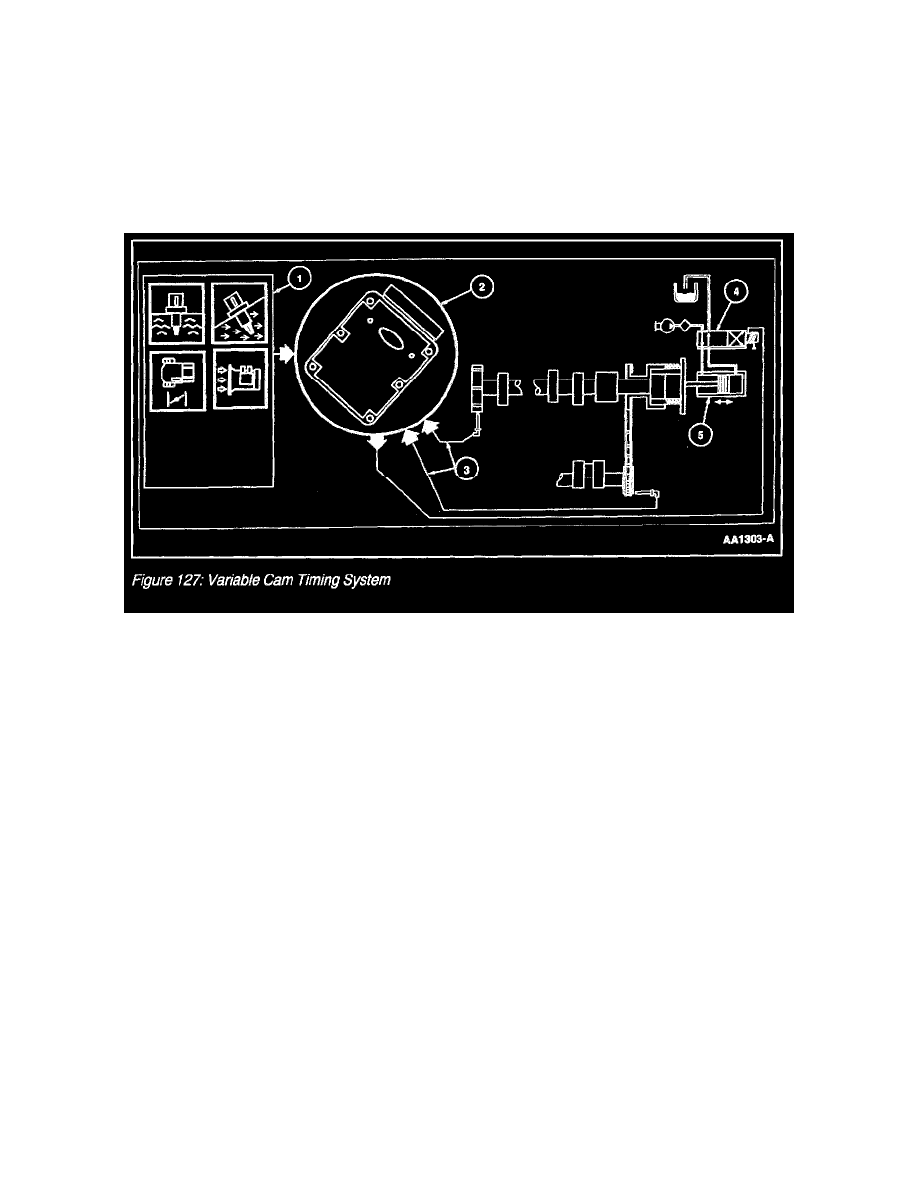
Variable Cam Timing System
Overview
The Variable Cam Timing System allows the exhaust cam to advance and retard at varying engine speeds. The purpose of this is to reduce exhaust
emissions and increase fuel economy. As the exhaust cam retards in relation to the crankshaft position, residual exhaust gases are left in the
combustion chamber. The residual gases cool the combustion chamber and are inert when mixed with the incoming fresh charge of fuel and air. This
results in better fuel economy and lower Nitrogen Oxides (NOx) and Hydrocarbons (HC) the engine produces. The Exhaust Gas Recalculation
System (EGR) is unnecessary on the 2.0L (4V) engine due to this feature.
Variable Cam Timing
Variable Cam Timing System
The Variable Cam Timing (VCT) System consists of the control solenoid, five-tooth pulse ring (4+1) on exhaust camshaft, Intake Air Temperature
(IAT) sensor, Engine Coolant Temperature (ECT) sensor, Camshaft Position (CMP) sensor, Mass Air Flow (MAF) sensor, Crankshaft Position
(CKP) sensor, Powertrain Control Module (PCM) (Figure 127).
1. The powertrain control module (PCM) receives input signals from the intake air temperature (IAT) sensor, engine coolant temperature (ECT)
sensor, camshaft position (CMP) sensor, mass air flow (MAF) sensor and crankshaft position (CKP) sensor for determining the operating
conditions of the engine.
2. The Variable Cam Timing (VCT) system is enabled by the PCM when the proper conditions are met. The PCM disables the VCT system if a
fault is detected.
3. The PCM calculates relative cam position using the CMP sensor and data from the (4+1) pulse ring mounted on the exhaust camshaft. Relative
cam position is calculated by measuring the time between the rising edge of Profile Ignition Pickup (PIP) and the falling edge of VCT pulse.
4. The PCM continually calculates a cam position error value based on the difference between the desired and actual position and a duty cycle is
commanded for the VCT solenoid valve. Engine oil is allowed to flow to the VCT unit.
5. Oil flows to either side of the piston chamber changing a linear motion from the piston to a rotation motion from the helical mechanism in the
VCT unit. During closed loop the PCM outputs a revised duty cycle to the VCT solenoid valve to correct for cam position error.
Hardware
Variable Cam Timing (VCT) Solenoid Valve