
Focus ZX5 L4-2.0L DOHC VIN 3 (2002)
2.
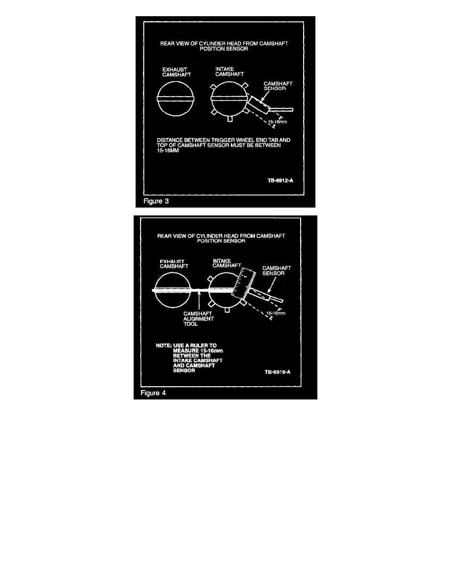
Inspect the intake camshaft position sensor trigger wheel alignment. With camshaft alignment tool, and crank timing peg installed, there should be
15-16 mm between the top edge of the CMP sensor and the CMP trigger wheel tooth (Figures 3 and 4).
a.
If trigger wheel alignment does not appear to be correct, replace the intake camshaft. Refer to Workshop Manual, Section 303-01C -
Camshafts.
b.
If trigger wheel alignment does appear correct, verify VCT Solenoid Wiring and connections. If OK, replace the VCT Solenoid assembly,
torque the VCT Solenoid retainer bolt to 88 Lb-in. (10 N.m).
3.
Reassemble. Refer to Workshop Manual Section 303-01C - Timing Belt, perform only the steps of this procedure that are necessary to reassemble
the engine.
NOTE
WHEN TORQUING THE INTAKE AND EXHAUST CAMSHAFT PULLEYS IT MAY BE NECESSARY TO USE LOCKING PLIERS TO
INSURE THE CAMS DO NOT MOVE. ALSO REMOVE THE CAMSHAFT ALIGNMENT BAR DURING THIS PROCEDURE TO PREVENT
CAMSHAFT BREAKAGE.
NOTE