
Focus ZX5 L4-2.0L DOHC VIN 3 (2002)
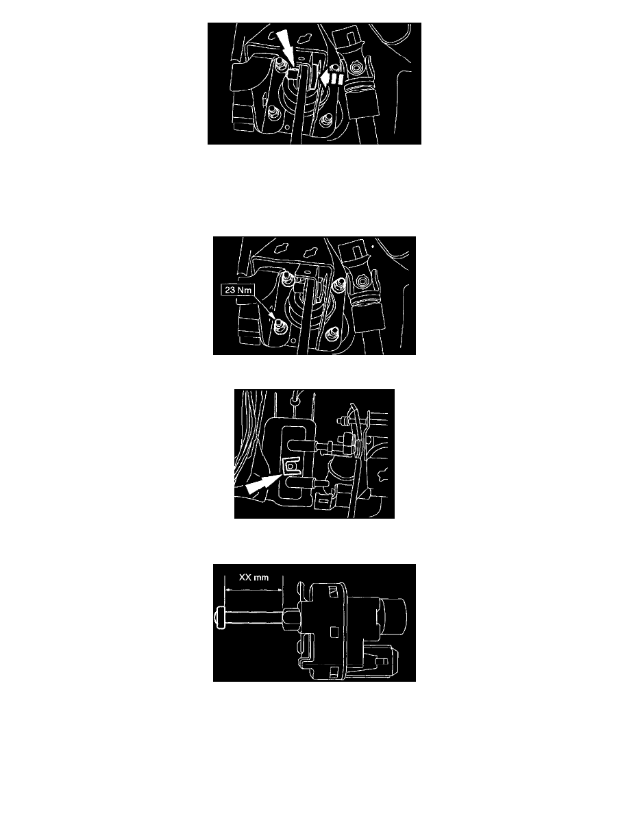
3. CAUTION: Make sure the brake pedal actuating rod retaining pin is locked in position. When correctly installed, the locking tab on the side of
the retaining pin will be visible as it extends through the actuating rod and the brake pedal.
CAUTION: Push and pull the retaining pin to make sure it is correctly installed.
Install the brake pedal actuating rod retaining pin.
4. Install the pedal assembly retaining nuts.
5. Attach the clutch slave cylinder supply line to the front bulkhead.
-
Install the clip.
6. NOTE: The clutch position switch (colored red) is not adjustable. Pull out the starter safety switch, speed control deactivation switch and stop
lamp switch plungers until they are fully extended.
Measure the plunger length.
-
Speed control deactivation switch (colored green) XX mm = 24 mm.
-
Stop lamp switch (colored gray) XX mm = 21 mm.
-
Starter safety switch (colored black) XX mm=26 mm.