
Freestar V6-4.2L VIN 2 (2004)
Part 3
3. NOTE: Make sure the battery negative cable is still disconnected before continuing with the installation portion of this procedure.
Remove the parts in the order indicated in the illustrations and tables.
Item 5: Quarter Trim Panel (RH) Removal Note
1. Separate the quarter trim panel enough to remove the D-pillar trim panel.
Item 14: Quarter Trim Panel (LH) Removal Note
1. Separate the quarter trim panel enough to remove the D-pillar trim panel.
Item 22: Headliner Removal Note
1. Separate the headliner from the roof, at the rear hatch area, to expose the bridge resistor.
-
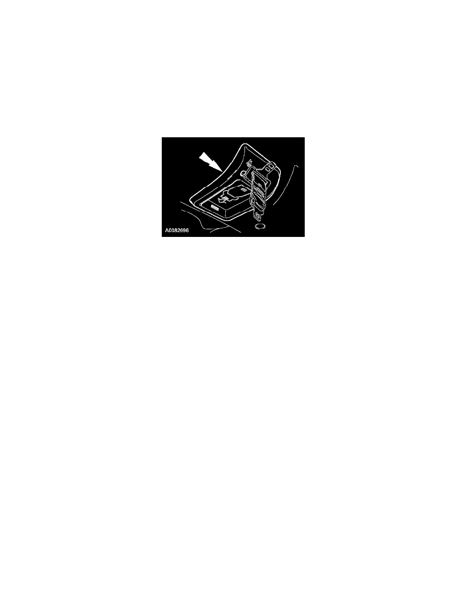
If equipped with third row seating, pull down to release the retainers and remove the safety belt retractor cover.
INSTALLATION
1. To install, reverse the removal procedure.
2. Connect the battery ground cable.
3. With the restraint system diagnostic tools installed at all deployable devices, prove out the supplemental restraint system (SRS). See: Air Bag(s)
Arming and Disarming/Service and Repair/Prove Out Procedure
4. Disconnect the battery ground cable and wait at least one minute.
5. WARNING: To reduce the risk of serious personal injury, read and follow all warnings, notes, and instructions in the supplemental
restraint system (SRS) deactivation/reactivation procedure. Refer to Air Bag(s) Arming and Disarming.
Reactivate the supplemental restraint system (SRS). Refer to Air Bag(s) Arming and Disarming.
6. Connect the battery ground cable.
7. WARNING: Restraint system diagnostic tools are for service only. Tools must be removed prior to operating the vehicle over the road.
Failure to remove restraint system diagnostic tools could result in injury and possible violation of vehicle safety standards.
With all the restraint system diagnostic tools removed, prove out the supplemental restraint system (SRS). See: Air Bag(s) Arming and
Disarming/Service and Repair/Prove Out Procedure
8. Check the active restraint system for correct operation.