
Freestar V6-4.2L VIN 2 (2004)
6.
Insert stripped wire into the buff splice, making sure the insulation on wire does not enter the butt splice (Figure 8).
7.
Holding the wire in place, squeeze tool handles together until ratchet releases. Allow tool handles to open, then remove crimped butt splice.
8.
To crimp the other half of the splice, reposition the un-crimped wire barrel in the same crimping chamber, and repeat Steps 3-8. If splice cannot be
turned for crimping the other half, turn the tool around.
9.
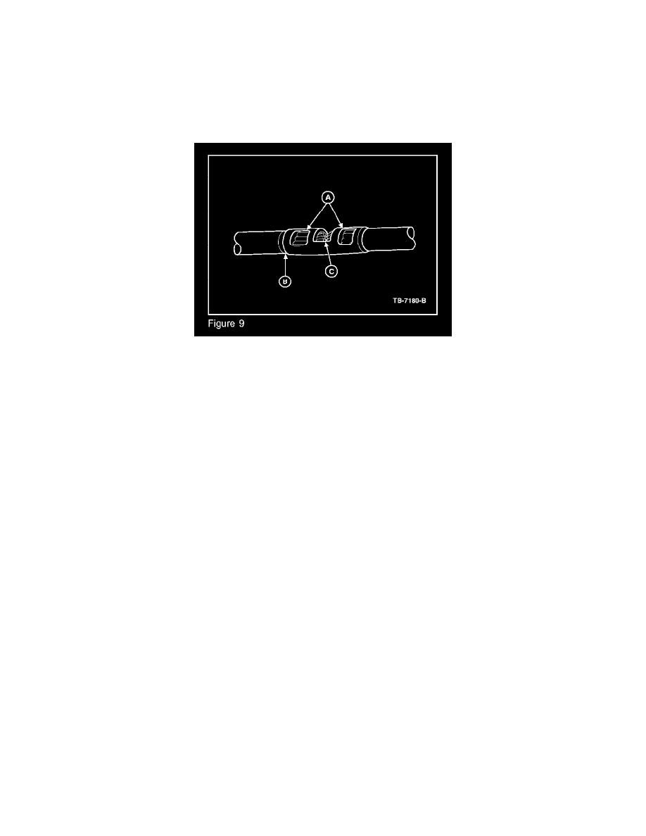
Check for acceptable crimp.
a.
Crimp should be centered on each end of the butt splice. It is acceptable for crimp to be slightly off center, but not off the end of the buff
splice (Figure 9-a).
b.
Wire insulation does not enter butt splice. Wire is flush with or extends slightly beyond end of buff splice (Figure 9-b).
c.
Wire is visible through inspection hole of splices (Figure 9-c).
10.
Evenly position heat shrink tubing over wire repair (Figure 5).
NOTE
OVERLAP TUBING ON BOTH WIRES.
11.
Use a shielded heat gun to heat the entire length of the heat shrink tubing until the hot melt appears from both ends of the tubing. Durability of a
heat shrink tubing splice is dependent on the hot melt that will appear from both ends of the tube. The hot melt forms an adhesive seal between the
wire insulation and the heat shrink tubing, which prevents air and moisture from entering the solder point (Figure 5).