Freestar V6-4.2L VIN 2 (2004)

TIME TO MATCH THE REST OF THE GRID.
5.
After five (5) minutes of dry time of the final coat of grid repair compound, remove the tape, step outside and inspect the repaired area. If the
repair compound is visible above or below the grid, the excess can be removed. This may be done by placing a single-edge razor blade on the back
window glass parallel to grid and scrape gently toward grid. A wider/thicker line will perform better but may not be cosmetically appealing.
CAUTION
BE CAREFUL NOT TO DAMAGE GRID LINE WITH RAZOR BLADE. VERIFY ALL OF THE GRID LINES FUNCTION PROPERLY WHEN
FINISHED.
Curing
The service coating will air-dry in approximately one (1) minute and the system can be energized after five minutes. Maximum hardness and adhesion
occur after approximately 24 hours.
SOLDER METHOD OF LEAD TERMINAL
NOTE
THE REAR WINDOW MUST BE AT A MINIMUM OF 60° F (16° C) BEFORE A REPAIR IS MADE.
PLACE PROTECTIVE COVERING OVER THE PACKAGE TRAY AS NECESSARY.
The new terminal will cover the original terminal location, but must be placed so that the new terminal conductive areas will be placed on a good
conductive base. This area should be cleaned with steel wool or an abrasive pad to remove grime from the buss-bar. The area should then be cleaned
with Ultra Clear Spray Glass Cleaner, ZC-23, or equivalent meeting Ford specification ESR-M14P5-A to remove all dirt, wax, grease, oil or other
foreign matter. It is important that the repair area be clean and dry and appear metallic. Depending on the buss-bar condition, rigorous polishing with
steel wool may be required. Please note that the entire buss-bar may be cleaned to improve appearance.
CAUTION
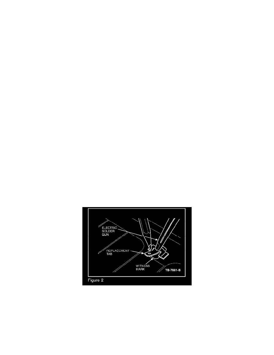
DO NOT USE ANY TYPE OF FLAME TORCH OR FLAME HEATED SOLDERING GUN FOR THIS PROCEDURE. TESTING INDICATED
INADEQUATE HEAT GENERATION AT THE TIP AND THE EXHAUST HEAT CAN CAUSE DAMAGE TO PLASTIC TRIM PARTS IN
THE AREA. USE ONLY AN ELECTRIC SOLDERING GUN WITH 100 WATTS OR MORE OF POWER.
BEFORE USING THE SOLDERING GUN, BE SURE TO MELT A SMALL AMOUNT OF ROSIN CORE SOLDER TO THE TIP. THE SOLDER
WILL ASSIST IN ACHIEVING BETTER HEAT TRANSFER FROM THE SOLDERING GUN TIP TO THE NEW TERMINAL.
The new terminal has pre-applied solder, flux and temperature sensitive paint. The paint provides a visual indication when the terminal has reached the
proper temperature to melt the solder on the terminal. When the proper temperature is achieved the temperature paint will liquefy and change color.
