
Fusion L4-2.3L VIN Z (2006)
The message center displays the last selected feature if there are no more warning messages. This allows full functionality of the message center by
pressing the message center switch RESET button to clear the warning message. Warning messages that have been reset are divided into 3 categories:
-
does not disappear until a condition has changed.
-
will reappear 10 minutes from pressing the RESET button.
-
does not reappear until the ignition switch LOCK/OFF to RUN cycle has been completed. This acts as a reminder that the warning conditions still
exist on the vehicle.
The system warning messages that cannot be reset are:
-
DRIVER DOOR AJAR
-
PASSENGER DOOR AJAR
-
REAR LEFT DOOR AJAR
-
REAR RIGHT DOOR AJAR
-
PARK BRAKE ENGAGED
The system warning messages that return after 10 minutes are:
-
LOW FUEL LEVEL
-
CHECK CHARGING SYSTEM
-
CHECK BRAKE SYSTEM
The system warning messages that return after the ignition switch is turned from the LOCK/OFF to RUN position are:
-
LOW BRAKE FLUID LEVEL
-
TRUNK AJAR
-
COMPASS ERROR (if equipped)
-
CHECK LEFT HEADLAMP
-
CHECK RIGHT HEADLAMP
-
CHECK LF TURN LAMP
-
CHECK RF TURN LAMP
-
CHECK LR TURN LAMP
-
CHECK RR TURN LAMP
-
INTEGRATED KEY PROGRAMMING STATUS (displayed when an attempt is made to program a fifth integrated key to the remote key entry
system) - only allows 4 integrated keys.
Inspection and Verification
INSPECTION AND VERIFICATION
1. Verify the customer concern.
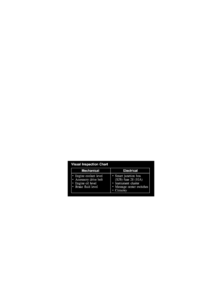
Visual Inspection Chart
2. Visually inspect for obvious signs of mechanical or electrical damage.
3. If an obvious cause for an observed or reported concern is found, correct the cause (if possible) before proceeding to the next step.
4. If the cause is not visually evident, connect the diagnostic tool to the data link connector (DLC) and select the vehicle to be tested from the
diagnostic tool menu. If the diagnostic tool does not communicate with the vehicle:
-
check that the program card is correctly installed.
-
check the connections to the vehicle.
-
check the ignition switch position.
5. If the diagnostic tool still does not communicate with the vehicle, refer to the diagnostic tool operating manual.
6. Carry out the diagnostic tool data link test. If the diagnostic tool responds with:
-
CAN circuit fault; all electronic control units no response/not equipped, refer to Information Bus (Module Communications Network).
-
No response/not equipped for the instrument cluster, refer to Instrument Cluster.
-
System passed, retrieve and record the continuous diagnostic trouble codes (DTCs), erase the continuous DTCs, and carry out self-test
diagnostics for the instrument cluster.
7. If the DTCs retrieved are related to the concern, refer to the Instrument Cluster Diagnostic Trouble Code (DTC) Index. See: Diagnostic Trouble