
Fusion L4-2.3L VIN Z (2006)
Brake Rotor/Disc: Service and Repair
Brake Disc Machining
Brake Disc Machining
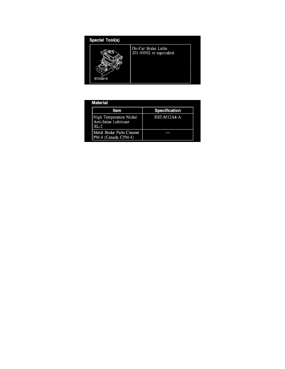
Special Tool(s)
Material
CAUTION: Do not use a bench lathe to machine the brake discs.
NOTE: Read the entire operating manual and view the video shipped with the lathe before installing, operating or repairing the lathe.
NOTE: Do not machine new brake discs.
NOTE: Lateral runout and disc thickness variation measurements are not required because correct adjustment of the on-vehicle brake lathe makes
sure that these dimensions are within specifications.
1. NOTE: It is not necessary to disconnect the brake line from the brake caliper.
Position the brake caliper and brake caliper anchor bracket (if equipped) aside.
2. Machine the brake disc using the on-car brake lathe.
1
Install the hub adapter and silencer belt, if necessary.
2
Install the cutting lathe.
3
If the lathe is not self adjusting, adjust the lathe oscillation using a dial indicator. The total indicated reading (TIR) target is 0.000 mm
(0.000 inch), and the maximum is 0.08 mm (0.003 inch).
4
Center the cutting head, adjust the cutting bits and install the chip deflector.
5
NOTE: The depth of cut should be between 0.10 and 0.20 mm (0.004 and 0.008 inch). Lighter cuts cause the bit to heat up and wear faster.
Heavier cuts cause poor brake disc surface finish.
Machine the brake disc.
6
Remove the lathe and, if installed, the silencer belt.
7
Remove the hub adapter.
3. Remove the metal shavings.
4. NOTE: It is not necessary to install new brake pads if the friction material measures within specification.
Install the brake caliper and brake caliper anchor bracket.