
Fusion L4-2.3L VIN Z (2006)
I5-I6
Normal Operation
The stoplamp switch is supplied voltage through circuit SBP04 (GN/RD) from the smart junction box (SJB). When the brake pedal is applied, the
stoplamp switch routes voltage to the SJB through circuit CCB08 (VT/WH).
For the Milan and Zephyr, the voltage is then routed to the stoplamps through circuit CLS17 (YE/GY).
Possible Causes
-
Fuse
-
Circuit CCB08 (VT/WH) open
-
Circuit CLS17 (YE/GY) open
-
Circuit SBP04 (GN/RD) open
-
Stoplamp switch
-
SJB
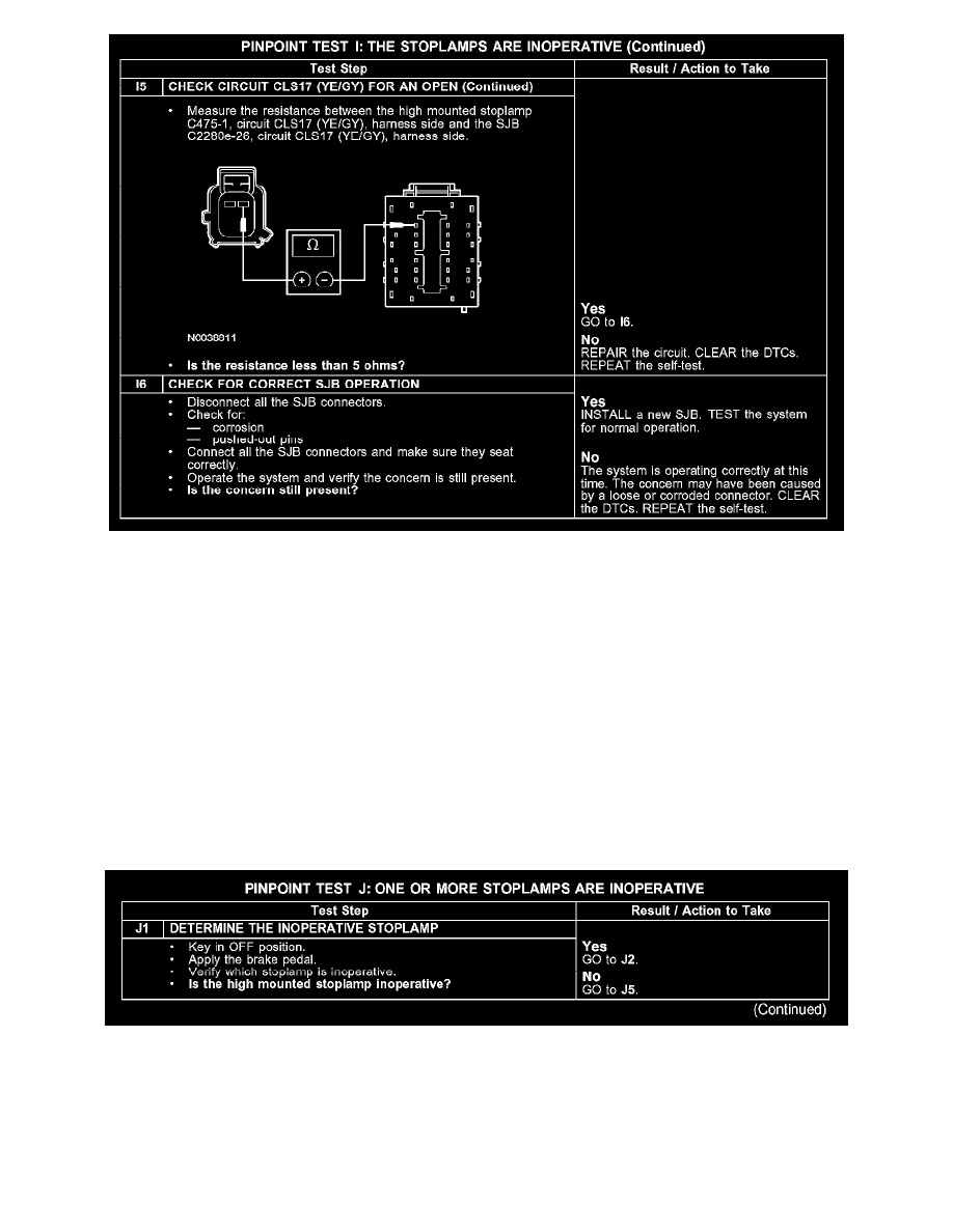
Test J: One Or More Stoplamps Are Inoperative
PINPOINT TEST J: ONE OR MORE STOPLAMPS ARE INOPERATIVE
J1