
Fusion L4-2.3L VIN Z (2006)
D2-D3
Normal Operation
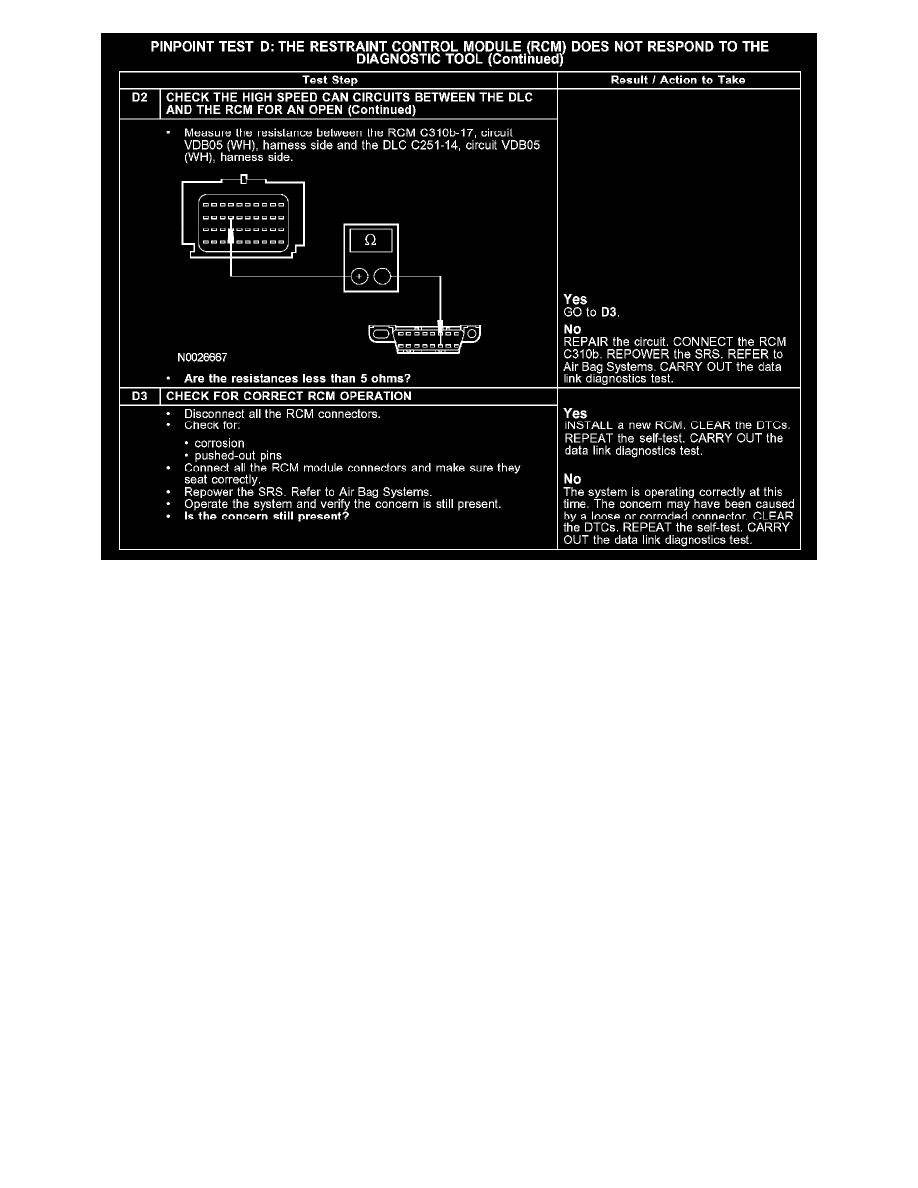
The RCM communicates with the diagnostic tool through the high speed controller area network (CAN), circuits VDB04 (WH/BU) and VDB05
(WH).
Check the high speed CAN circuits VDB04 (WH/BU) and VDB05 (WH) between the RCM C310b and the data link connector (DLC) C251. The
total resistance values must not be more than 5 ohms. If the resistance is more than 5 ohms there is an open in one of the high speed CAN circuits,
damage to the DLC C251, damage to the RCM C310b, or a problem in an in-line connector.
Possible Causes
-
high speed CAN data plus circuit VDB04 (WH/BU) open
-
high speed CAN data minus circuit VDB05 (WH) open
-
RCM C310b
-
RCM
Test E: The Occupant Classification Sensor Does Not Respond To The Diagnostic Tool
PINPOINT TEST E: THE OCCUPANT CLASSIFICATION SENSOR DOES NOT RESPOND TO THE DIAGNOSTIC TOOL