
Fusion L4-2.3L VIN Z (2006)
2
"D" DRIVE
3
"N" NEUTRAL
4
"R" REVERSE
5
"P" PARK
^
When in position "D" the marks on the manual control lever line up with the marks on the TR sensor.
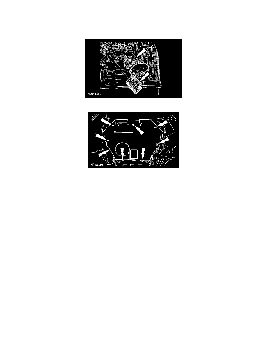
5. Connect the selector lever cable and the TR sensor electrical connector.
6. Install the splash shield and the 7 bolts.