| PINPOINT TEST B : REAR FOG LAMP(S) OR FRONT FOG LAMPS INOPERATIVE |
| TEST CONDITIONS | DETAILS/RESULTS/ACTIONS |
| B1: DETERMINE THE FAULT CONDITION |
| | 1 Ignition switch in position II. |
| | 2 Check operation of the fog lamps. |
| | 3 Switch on the front fog lamps. |
| | 4 Switch on rear fog lamp(s) |
| | Do the front fog lamps illuminate? Yes No |
| B2: CHECK THE HEADLIGHT SWITCH |
| | 1 Ignition switch in position 0. |
| | 2 Disconnect headlight switch from connector C338. |
| | 3 Connect a fused jumper wire (20 A) at the headlamp switch, connector C338, between pin 7, circuit 15-LD10 (GN/OG) and pin 2, circuit 15S-LD6A (GN/YE), wiring harness side. |
| | 4 Ignition switch in position II. |
| | 5 Switch on rear fog lamp(s) |
| | Does/Do the rear fog lamp(s) illuminate? Yes INSTALL A NEW headlight switch. CHECK the operation of the system. No - LHD/RHD without trailer socket, built from 08/2005: LOCATE and RECTIFY the break in the circuits between the headlamp switch and soldered connection S19 using the Wiring Diagrams. CHECK the operation of the system. - LHD, vehicles without trailer socket, built before 08/2005: GO to B3. - RHD, vehicles without trailer socket, built before 08/2005: GO to B4. - LHD, vehicles with trailer socket, built before 08/2005: GO to B5. - RHD, vehicles with trailer socket, built before 08/2005: GO to B14. |
| B3: CHECK GROUND CONNECTION OF REAR FOG LAMP (LHD) |
| | 1 Ignition switch in position 0. |
| | 2 Disconnect left-hand rear lamp assembly from connector C333. |
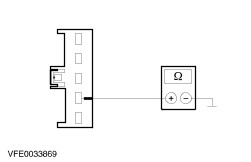
| | 3 Measure the resistance between the left-hand rear lamp assembly, connector C333, pin 4, circuit 31-LF23 (BK), wiring harness side and ground. |
| | Is a resistance of less than 2 ohms registered? Yes LOCATE and RECTIFY the break in circuit 15S-LD6A (GN/YE) or 15S-LD6 (GN/YE) between the headlight switch and the rear lamp assembly using the wiring diagrams. CHECK and INSTALL A NEW rear lamp assembly if necessary. CHECK the operation of the system. No LOCATE and RECTIFY the break in circuit 31-LF23 (BK) between the rear lamp assembly and soldered connection S24 using the wiring diagrams. CHECK the operation of the system. |
| B4: CHECK GROUND CONNECTION OF REAR FOG LAMP (RHD) |
| | 1 Ignition switch in position 0. |
| | 2 Disconnect right-hand rear lamp assembly from connector C348. |
| | 3 Measure the resistance between the right-hand rear lamp assembly, connector C348, pin 4, circuit 31-LF24 (BK), wiring harness side and ground. |
| | Is a resistance of less than 2 ohms registered? Yes LOCATE and RECTIFY the break in circuit 15S-LD6A (GN/YE) or 15S-LD6 (GN/YE) between the headlight switch and the rear lamp assembly using the wiring diagrams. CHECK and INSTALL A NEW rear lamp assembly if necessary. CHECK the operation of the system. No LOCATE and RECTIFY the break in circuit 31-LF24 (BK), between the rear lamp assembly and ground connection G18 using the Wiring Diagrams. CHECK the operation of the system. |
| B5: CHECK GROUND CONNECTION OF REAR FOG LAMP (LHD) |
| | 1 Ignition switch in position 0. |
| | 2 Disconnect left-hand rear lamp assembly from connector C333a. |
| | 3 Measure the resistance between the left-hand rear lamp assembly, connector C333a, pin 4: - Vehicles built from 03/2004, with 13-pin trailer socket: circuit (BN), wiring harness side and ground.
- All other models: circuit (GN), wiring harness side and ground.
|
| | Is a resistance of less than 2 ohms registered? Yes No - Vehicles built from 03/2004, with 13-pin trailer socket: LOCATE and RECTIFY the break in circuit (BN) between the rear lamp assembly and soldered connection S1008 using the Wiring Diagrams. CHECK the operation of the system. - All other models: LOCATE and RECTIFY the break in circuit (GN) or 31-LF23 (BK) between the rear lamp assembly and soldered connection S24 using the Wiring Diagrams. CHECK the operation of the system. |
| B6: CHECK CIRCUITS 15S-LD6(A) (GN/YE) OR (RD/WH) FOR OPEN CIRCUIT |
| | 1 Ignition switch in position 0. |
| | 2 Connect Headlamp switch to connector C338. |
| | 3 Disconnect Vehicles built before 03/2004: Trailer control unit from connector C1030. |
| | 4 Disconnect Vehicles built from 03/2004: Rear fog lamp cut-off relay from socket C1043. |
| | 5 Ignition switch in position II. |
| | 6 Switch on the REAR FOG LIGHT. |
| | 7 Vehicles built before 03/2004: Measure the voltage between the trailer control unit, connector C1030, pin 4, circuit (RD/WH), wiring harness side and ground. |
| | 8 Vehicles built from 03/2004: Measure the voltage between the rear fog lamp cut-off relay, socket C1043, circuit (RD/WH), wiring harness side and ground. |
| | Is battery voltage measured? Yes - Vehicles built before 03/2004: GO to B7. No - Vehicles built before 03/2004: LOCATE and RECTIFY the break in circuit(s) 15S-LD6(A) (GN/YE) or (RD/WH) between the headlamp switch and the trailer control unit using the Wiring Diagrams. CHECK the operation of the system. - Vehicles built from 03/2004: LOCATE and RECTIFY the break in circuit(s) 15S-LD6(A) (GN/YE) or (RD/WH) between the headlamp switch and the rear fog lamp cut-off relay using the Wiring Diagrams. CHECK the operation of the system. |
| B7: CHECK THE TRAILER CONTROL UNIT |
| | 1 Ignition switch in position 0. |
| | 2 Connect Left-hand rear lamp assembly to connector C333a. |
| | 3 Connect a fused jumper wire (20 A) at the trailer control unit, connector C1030, between pin 4, circuit (RD/WH) and pin 6, circuit (VT/YE), wiring harness side. |
| | 4 Ignition switch in position II. |
| | 5 Switch on the REAR FOG LIGHT. |
| | Does the rear fog lamp illuminate? Yes No LOCATE and RECTIFY the break in circuit (VT/YE) between the trailer control unit and rear lamp assembly using the wiring diagrams. CHECK and INSTALL A NEW rear lamp assembly if necessary. CHECK the operation of the system. |
| B8: CHECK FUSE |
| | 1 Ignition switch in position 0. |
| | 2 Disconnect Fuse. - Vehicles built before 10/2002: F31 (20 A) (CJB)
- Vehicles built from 10/2002: F56 (20 A) (CJB)
|
| | 3 CHECK Fuse. - Vehicles built before 10/2002: F31 (20 A) (CJB)
- Vehicles built from 10/2002: F56 (20 A) (CJB)
|
| | Is the fuse OK.? Yes No INSTALL A NEW fuse F31 (20 A) or F56 (20 A) and check the operation of the system. If the fuse blows again, LOCATE and RECTIFY the short to ground using the Wiring Diagrams. CHECK the operation of the system. |
| B9: CHECK VOLTAGE AT FUSE |
| | 1 Connect Fuse. - Vehicles built before 10/2002: F31 (20 A) (CJB)
- Vehicles built from 10/2002: F56 (20 A) (CJB)
|
| | 2 Ignition switch in position II. |
| | 3 Measure the voltage between: - Vehicles built before 10/2002: Fuse F31 (20 A) (CJB) and ground.
- Vehicles built from 10/2002: F56 (20 A) (CJB) and ground.
|
| | Is battery voltage measured? Yes No - Vehicles built before 10/2002: RECTIFY the break in the voltage supply of fuse F31 (20A) (CJB) using the Wiring Diagrams. CHECK and INSTALL A NEW CJB if necessary. CHECK the operation of the system. - Vehicles built from 10/2002: RECTIFY the break in the voltage supply of fuse F56 (20A) (CJB) using the Wiring Diagrams. CHECK and INSTALL A NEW CJB if necessary. CHECK the operation of the system. |
| B10: CHECK THE VOLTAGE SUPPLY OF THE TRAILER CONTROL UNIT |
| | 1 Ignition switch in position 0. |
| | 2 Disconnect trailer control unit from connector C1041. |
| | 3 Ignition switch in position II. |
| | 4 Measure the voltage between the trailer control unit, connector C1041, pin 8, circuit (RD), wiring harness side and pin 10, circuit (RD), wiring harness side and ground. |
| | Is battery voltage registered following both measurements? Yes No - Vehicles built before 10/2002: LOCATE and RECTIFY the break in the circuit between fuse F31 (20 A) (CJB) and the trailer control unit using the Wiring Diagrams. CHECK and INSTALL A NEW rear lamp assembly if necessary. CHECK the operation of the system. - Vehicles built from 10/2002: LOCATE and RECTIFY the break in the circuit between fuse F56 (20 A) (CJB) and the trailer control unit using the Wiring Diagrams. CHECK and INSTALL A NEW rear lamp assembly if necessary. CHECK the operation of the system. |
| B11: CHECK THE GROUND CONNECTION OF THE TRAILER CONTROL UNIT |
| | 1 Ignition switch in position 0. |
| | 2 Measure the resistance between the trailer control unit, connector C1041, pin 1, circuit (BN), wiring harness side and ground. |
| | Is a resistance of less than 2 ohms registered? Yes RENEW the trailer control unit. CHECK the operation of the system. No LOCATE and RECTIFY the break in the circuit (BN) between the trailer control unit and ground connection G18 using the wiring diagrams. CHECK the operation of the system. |
| B12: CHECK THE REAR FOG LAMP CUT-OFF RELAY |
| | 1 Ignition switch in position 0. |
| | 2 Connect Left-hand rear lamp assembly to connector C333a. |
| | 3 Connect a fused jumper wire (20 A) at the rear fog lamp cut-off relay, socket C1043, between circuit (RD/WH) and circuit (VT/YE), socket side. |
| | 4 Ignition switch in position II. |
| | 5 Switch on the REAR FOG LIGHT. |
| | Does the rear fog lamp illuminate? Yes No LOCATE and RECTIFY the break in the circuit (VT/YE) between the rear fog lamp cut-off relay and the rear lamp assembly using the Wiring Diagrams. CHECK and INSTALL A NEW rear lamp assembly if necessary. CHECK the operation of the system. |
| B13: CHECK THE GROUND CONNECTION OF THE REAR FOG LAMP CUT-OFF RELAY |
| | 1 Ignition switch in position 0. |
| | 2 Measure the resistance between the rear fog lamp cut-off relay, socket C1043, circuit (BN), wiring harness side and ground. |
| | Is a resistance of less than 2 ohms registered? Yes RENEW the rear fog lamp cut-off relay. CHECK the operation of the system. No - Vehicles with 7 pin trailer socket: LOCATE and RECTIFY the break in circuit (BN) or 31-LF24 (BK) between the rear lamp cut-off relay and ground connection G18 using the Wiring Diagrams. CHECK the operation of the system. - Vehicles with 13 pin trailer socket: LOCATE and RECTIFY the break in circuit (BN) between the rear fog lamp cut-off relay and soldered connection S1008 using the Wiring Diagrams. CHECK the operation of the system. |
| B14: CHECK GROUND CONNECTION OF REAR FOG LAMP (RHD) |
| | 1 Ignition switch in position 0. |
| | 2 Disconnect right-hand rear lamp assembly from connector C348a. |
| | 3 Measure the resistance between the right-hand rear lamp assembly, connector C348a, pin 4: - Vehicles built before 03/2004: circuit (BK), wiring harness side and ground.
- Vehicles built from 03/2004: circuit (BN), wiring harness side and ground.
|
| | Is a resistance of less than 2 ohms registered? Yes No - Vehicles built before 03/2004: LOCATE and RECTIFY the break in circuit (BK) or 31-LF24 (BK) between the rear lamp assembly and ground connection G18 using the Wiring Diagrams. CHECK the operation of the system. - Vehicles built from 03/2004: LOCATE and RECTIFY the break in circuit (BN) or 31-LF24 (BK) between the rear lamp assembly and ground connection G18 using the Wiring Diagrams. CHECK the operation of the system. |
| B15: CHECK CIRCUITS 15S-LD6(A) (GN/YE), (VT/OG), (BK/BU) AND (RD/WH) FOR OPEN CIRCUIT |
| | 1 Ignition switch in position 0. |
| | 2 Connect Headlamp switch to connector C338. |
| | 3 Disconnect Vehicles built before 03/2004: Trailer control unit from connector C1030. |
| | 4 Disconnect Vehicles built from 03/2004: Rear fog lamp cut-off relay from socket C1043. |
| | 5 Ignition switch in position II. |
| | 6 Switch on the REAR FOG LAMP. |
| | 7 Vehicles built before 03/2004: Measure the voltage between the trailer control unit, connector C1030, pin 4, circuit (RD/WH), wiring harness side and ground. |
| | 8 Vehicles built from 03/2004: Measure the voltage between the rear fog lamp cut-off relay, socket C1043, circuit (RD/WH), socket side and ground. |
| | Is battery voltage measured? Yes No - Vehicles built before 03/2004: LOCATE and RECTIFY the break in circuit(s) 15S-LD6(A) (GN/YE), (VT/OG) or (RD/WH) between the headlamp switch and the trailer control unit using the Wiring Diagrams. CHECK the operation of the system. - Vehicles built from 03/2004: LOCATE and RECTIFY the break in circuit(s) 15S-LD6(A) (GN/YE), (BK/BU) or (RD/WH) between the headlamp switch and the rear fog lamp cut-off relay using the Wiring Diagrams. CHECK the operation of the system. |
| B16: CHECK THE TRAILER CONTROL UNIT |
| | 1 Ignition switch in position 0. |
| | 2 Connect Right-hand rear lamp assembly to connector C348a. |
| | 3 Using a fused test cable (20 A) at the trailer control unit, connector C1030, bridge between pin 4, circuit (RD/WH) and pin 6, circuit (VT/YE), wiring harness side. |
| | 4 Ignition switch in position II. |
| | 5 Switch on the REAR FOG LIGHT. |
| | Does the rear fog lamp illuminate? Yes No LOCATE and RECTIFY the break in circuit (VT/YE) or (BK/BU) between the trailer control unit and rear lamp assembly using the Wiring Diagrams. CHECK and INSTALL A NEW rear lamp assembly if necessary. CHECK the operation of the system. |
| B17: CHECK FUSE |
| | 1 Ignition switch in position 0. |
| | 2 Disconnect Fuse. - Vehicles built before 10/2002: F31 (20 A) (CJB)
- Vehicles built from 10/2002: F56 (20 A) (CJB)
|
| | 3 CHECK Fuse. - Vehicles built before 10/2002: F31 (20 A) (CJB)
- Vehicles built from 10/2002: F56 (20 A) (CJB)
|
| | Is the fuse OK.? Yes No INSTALL A NEW fuse F31 (20 A) or F56 (20 A) (CJB) and check the operation of the system. If the fuse blows again, LOCATE and RECTIFY the short to ground using the Wiring Diagrams. CHECK the operation of the system. |
| B18: CHECK VOLTAGE AT FUSE |
| | 1 Connect Fuse. - Vehicles built before 10/2002: F31 (20 A) (CJB)
- Vehicles built from 10/2002: F56 (20 A) (CJB)
|
| | 2 Ignition switch in position II. |
| | 3 Measure the voltage between: - Vehicles built before 10/2002: Fuse F31 (20 A) (CJB) and ground.
- Vehicles built from 10/2002: F56 (20 A) (CJB) and ground.
|
| | Is battery voltage measured? Yes No - Vehicles built before 10/2002: RECTIFY the break in the voltage supply to fuse F31 (20 A) (CJB) using the Wiring Diagrams. CHECK and INSTALL A NEW CJB if necessary. CHECK the operation of the system. - Vehicles built from 10/2002: RECTIFY the break in the voltage supply of fuse F56 (20A) (CJB) using the Wiring Diagrams. CHECK and INSTALL A NEW CJB if necessary. CHECK the operation of the system. |
| B19: CHECK THE VOLTAGE SUPPLY OF THE TRAILER CONTROL UNIT |
| | 1 Ignition switch in position 0. |
| | 2 Disconnect trailer control unit from connector C1041. |
| | 3 Ignition switch in position II. |
| | 4 Measure the voltage between the trailer control unit, connector C1041, pin 8, circuit (RD), wiring harness side and pin 10, circuit (RD), wiring harness side and ground. |
| | Is battery voltage registered following both measurements? Yes No - Vehicles built before 10/2002: LOCATE and RECTIFY the break in the circuit between fuse F31 (20 A) (CJB) and the trailer control unit using the Wiring Diagrams. CHECK and INSTALL A NEW rear lamp assembly if necessary. CHECK the operation of the system. - Vehicles built from 10/2002: LOCATE and RECTIFY the break in the circuit between fuse F56 (20 A) (CJB) and the trailer control unit using the Wiring Diagrams. CHECK and INSTALL A NEW rear lamp assembly if necessary. CHECK the operation of the system. |
| B20: CHECK THE GROUND CONNECTION OF THE TRAILER CONTROL UNIT |
| | 1 Ignition switch in position 0. |
| | 2 Measure the resistance between the trailer control unit, connector C1041, pin 1, circuit (BN), wiring harness side and ground. |
| | Is a resistance of less than 2 ohms registered? Yes RENEW the trailer control unit. CHECK the operation of the system. No LOCATE and RECTIFY the break in the relevant circuit (BN) between the trailer control unit and ground connection G18 using the Wiring Diagrams. CHECK the operation of the system. |
| B21: CHECK REAR FOG LAMP CUT-OFF RELAY |
| | 1 Ignition switch in position 0. |
| | 2 Connect Right-hand rear lamp assembly to connector C348a. |
| | 3 Connect a fused jumper wire (20 A) at the rear fog lamp cut-off relay, socket C1043, between circuit (RD/WH) and circuit (VT/YE), socket side. |
| | 4 Ignition switch in position II. |
| | 5 Switch on the REAR FOG LAMP. |
| | Does the rear fog lamp illuminate? Yes No LOCATE and RECTIFY the break in circuit (VT/YE) or (WH/BK) between the rear fog lamp cut-off relay and the rear lamp assembly using the Wiring Diagrams. CHECK and INSTALL A NEW rear lamp assembly if necessary. CHECK the operation of the system. |
| B22: CHECK THE GROUND CONNECTION OF THE REAR FOG LAMP CUT-OFF RELAY |
| | 1 Ignition switch in position 0. |
| | 2 Measure the resistance between the rear fog lamp cut-off relay, socket C1043, circuit (BN), wiring harness side and ground. |
| | Is a resistance of less than 2 ohms registered? Yes RENEW the rear fog lamp cut-off relay. CHECK the operation of the system. No - Vehicles with 7 pin trailer socket: LOCATE and RECTIFY the break in circuit (BN) or 31-LF24 (BK) between the rear fog lamp cut-off relay and ground connection G18 using the Wiring Diagrams. CHECK the operation of the system. - Vehicles with 13 pin trailer socket: LOCATE and RECTIFY the break in circuit (BN) between the rear fog lamp cut-off relay and soldered connection S1008 using the Wiring Diagrams. CHECK the operation of the system. |
| B23: CHECK THE HEADLIGHT SWITCH |
| | 1 Ignition switch in position 0. |
| | 2 Disconnect headlight switch from connector C338. |
| | 3 Connect a fused jumper wire (20 A) at the headlamp switch, connector C338, between pin 7, circuit 15-LD10 (GN/OG) and pin 3, circuit 15S-LD5A (GN/BU) wiring harness side. |
| | 4 Ignition switch in position II. |
| | 5 CHECK the front fog lamps. |
| | Do the front fog lamps illuminate? Yes INSTALL A NEW headlight switch. CHECK the operation of the system. No - Vehicles built from 10/2004: LOCATE and RECTIFY the break in circuit 15S-LD5(A) (GN/BU) between the headlamp switch and soldered connection S38 using the Wiring Diagrams. CHECK the operation of the system. |
| B24: CHECK THE GROUND CONNECTION OF THE FRONT FOG LAMPS |
| | 1 Ignition switch in position 0. |
| | 2 Disconnect right-hand front fog lamp from connector C421. |
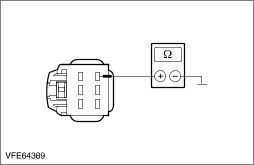
| | 3 Vehicles built before 08/2005: Measure the resistance between right-hand front fog lamp, connector C421, pin 2, circuit 31-LD17 (BK), wiring harness side and ground. |
| | 4 Vehicles built from 08/2005: Measure the resistance between right-hand front fog lamp, connector C421, pin 2, circuit 31-LD17 (BK), wiring harness side and ground. |
| | Is a resistance of less than 2 ohms registered? Yes LOCATE and RECTIFY the break in circuit 15S-LD5A (GN/BU) or 15S-LD5 (GN/BU), between the headlight switch and soldered connection S241 using the wiring diagrams. CHECK the operation of the system. No LOCATE and RECTIFY the break in the circuit between soldered connection S242 and ground connection G4 using the wiring diagrams. CHECK the operation of the system. |