| PINPOINT TEST A : SERVICE MODE CANNOT BE ACTIVATED |
| TEST CONDITIONS | DETAILS/RESULTS/ACTIONS |
| A1: CHECK FUSE F24 |
| | 1 Ignition switch in position 0. |
| | 2 CHECK Fuse F24 (CJB). |
| | Is the fuse OK? Yes No RENEW fuse F24 (20 A). CHECK the operation of the system. If the fuse blows again, LOCATE and RECTIFY the short to ground with the aid of the Wiring Diagrams. |
| A2: TEST VOLTAGE AT FUSE F24 |
| | 1 Connect Fuse F24 (CJB). |
| | 2 Measure the voltage between fuse F24 (20 A) and ground. |
| | Does the meter display battery voltage? Yes No REPAIR the voltage supply to fuse F24 with the aid of the Wiring Diagrams. CHECK operation of system. |
| A3: CHECK FUSE F38 |
| | 1 CHECK Fuse F38 (CJB). |
| | Is the fuse OK? Yes No RENEW fuse F38 (7.5 A). CHECK operation of system. If the fuse blows again, LOCATE and RECTIFY the short to ground with the aid of the Wiring Diagrams. |
| A4: CHECK THE VOLTAGE AT FUSE F38 |
| | 1 Connect Fuse F38 (CJB). |
| | 2 Ignition switch in position II. |
| | 3 Measure the voltage between fuse F38 (7.5 A) and ground. |
| | Does the meter display battery voltage? Yes No REPAIR the voltage supply to fuse F38 with the aid of the Wiring Diagrams. CHECK operation of system. |
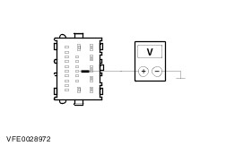
| A5: CHECK THE VOLTAGE AT THE GENERIC ELECTRONIC MODULE (GEM) |
| | 1 Ignition switch in position 0. |
| | 2 Disconnect GEM C318 (blue). |
| | 3 Measure the voltage between the GEM, connector C318, pin 2, circuit 29-AA80 (OG/WH), wiring harness side and ground. |
| | Does the meter display battery voltage? Yes No LOCATE and RECTIFY the break in circuit 29-AA80 (OG/WH) between GEM and fuse F24 with the aid of the Wiring Diagrams. CHECK operation of system. |
| A6: CHECK THE VOLTAGE AT THE GEM |
| | 1 Disconnect GEM C319 (white). |
| | 2 Ignition switch in position II. |
| | 3 Measure the voltage between the GEM, connector C319, pin 10, circuit 15-DK20 (GN/OG), wiring harness side and ground. |
| | Does the meter display battery voltage? Yes No LOCATE and RECTIFY the break in circuit 15-DK20 (GN/OG) between the GEM and solder point S3 with the aid of the Wiring Diagrams. CHECK operation of system. |
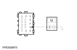
| A7: TEST THE GEM GROUND CONNECTION |
| | 1 Ignition switch in position 0. |
| | 2 Disconnect GEM C316 (black). |
| | 3 Measure the resistance between the GEM, connector C316, pin 2, circuit 31-DK20 (BK), wiring harness side and ground. |
| | Is a resistance of less than 2 Ohm registered? Yes No LOCATE and REPAIR the break in the circuit between the GEM and ground point G13 with the aid of the Wiring Diagrams. CHECK operation of system. |
| A8: TEST THE GEM GROUND CONNECTION |
| | 1 Disconnect GEM C320 (brown). |
| | 2 Measure the resistance between the GEM, connector C320, pin 2, circuit 91-DK20 (BK/RD), wiring harness side and ground. |
| | Is a resistance of less than 2 Ohm registered? Yes No LOCATE and RECTIFY the break in circuit 91-DK20 (BK/RD) between the GEM and ground connection G14 with the aid of the Wiring Diagrams. CHECK the operation of the system. |
| A9: CHECK THE CONTROL IMPULSE OF THE HEATED REAR WINDOW SWITCH |
| | 1 Operate the heated rear window switch and keep it operated. |
| | 2 Measure the resistance between the GEM, connector C320, pin 11, circuit 31S-HB22 (BK/GN), wiring harness side and ground. |
| | Is a resistance of less than 2 Ohm registered? Yes No |
| A10: CHECK THE SWITCH OF THE HEATED REAR WINDOW |
| | 1 Release the switch of the heated rear window. |
| | 2 Measure the resistance between the GEM, connector C320, pin 11, circuit 31S-HB22 (BK/GN), wiring harness side and ground. |
| | Is a resistance of more than 10 kOhms measured? Yes TEST the GEM and RENEW as necessary. CHECK the operation of the system. No |
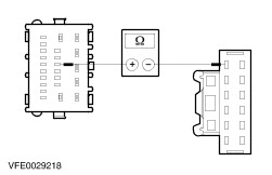
| A11: CHECK THE CIRCUIT BETWEEN THE GEM AND THE INTEGRATED CONTROL ASSEMBLY FOR A SHORT TO GROUND |
| | 1 Disconnect Integrated control assembly C714. |
| | 2 Measure the resistance between the GEM, connector C320, pin 11, circuit 31S-HB22 (BK/GN), wiring harness side and ground. |
| | Is a resistance of more than 10 kOhms measured? Yes RENEW the integrated control assembly. CHECK the operation of the system. No LOCATE and RECTIFY the short to ground in circuit 31S-HB22 (BK/GN) with the aid of the Wiring Diagrams. CHECK operation of system. |
| A12: TEST THE CIRCUIT BETWEEN THE GEM AND THE INTEGRATED CONTROL ASSEMBLY FOR OPEN CIRCUIT |
| | 1 Disconnect Integrated control assembly C714. |
| | 2 Measure the resistance between the GEM, connector C320, pin 11, circuit 31S-HB22 (BK/GN), wiring harness side and the integrated control assembly, connector C714, pin 1, circuit 31S-HB22 (BK/GN), wiring harness side. |
| | Is a resistance of less than 2 Ohm registered? Yes No LOCATE and REPAIR the break in circuit 31S-HB22 (BK/GN) between the GEM and the integrated control assembly with the aid of the Wiring Diagrams. CHECK the operation of the system. |
| A13: TEST THE GROUND CONNECTION OF THE INTEGRATED CONTROL ASSEMBLY |
| | 1 Measure the resistance between the integrated control assembly, connector C714, pin 9, circuit 31-DK1 (BK), wiring harness side and ground. |
| | Is a resistance of less than 2 Ohm registered? Yes RENEW the integrated control assembly. CHECK the operation of the system. No LOCATE and RECTIFY the break in circuit 31-DK1 (BK) between the integrated control assembly and soldered connection S265 with the aid of the Wiring Diagrams. CHECK the operation of the system. |