
Fusion AWD L4-2.3L (2008)
^
Discard the 7 nuts and the gasket.
11. Remove and discard the 7 catalytic converter manifold studs.
12. Clean and inspect the catalytic converter manifold.
Installation
1. Install the 7 new catalytic converter manifold studs.
^
Tighten to 17 Nm (13 lb-ft).
2. Position a new catalytic converter manifold gasket on the studs.
3. CAUTION: Failure to tighten the catalytic converter manifold nuts to specification before installing the converter bracket bolts will
cause the converter to develop an exhaust leak.
CAUTION: Failure to tighten the catalytic converter manifold nuts to specification a second time will cause the converter to develop an
exhaust leak.
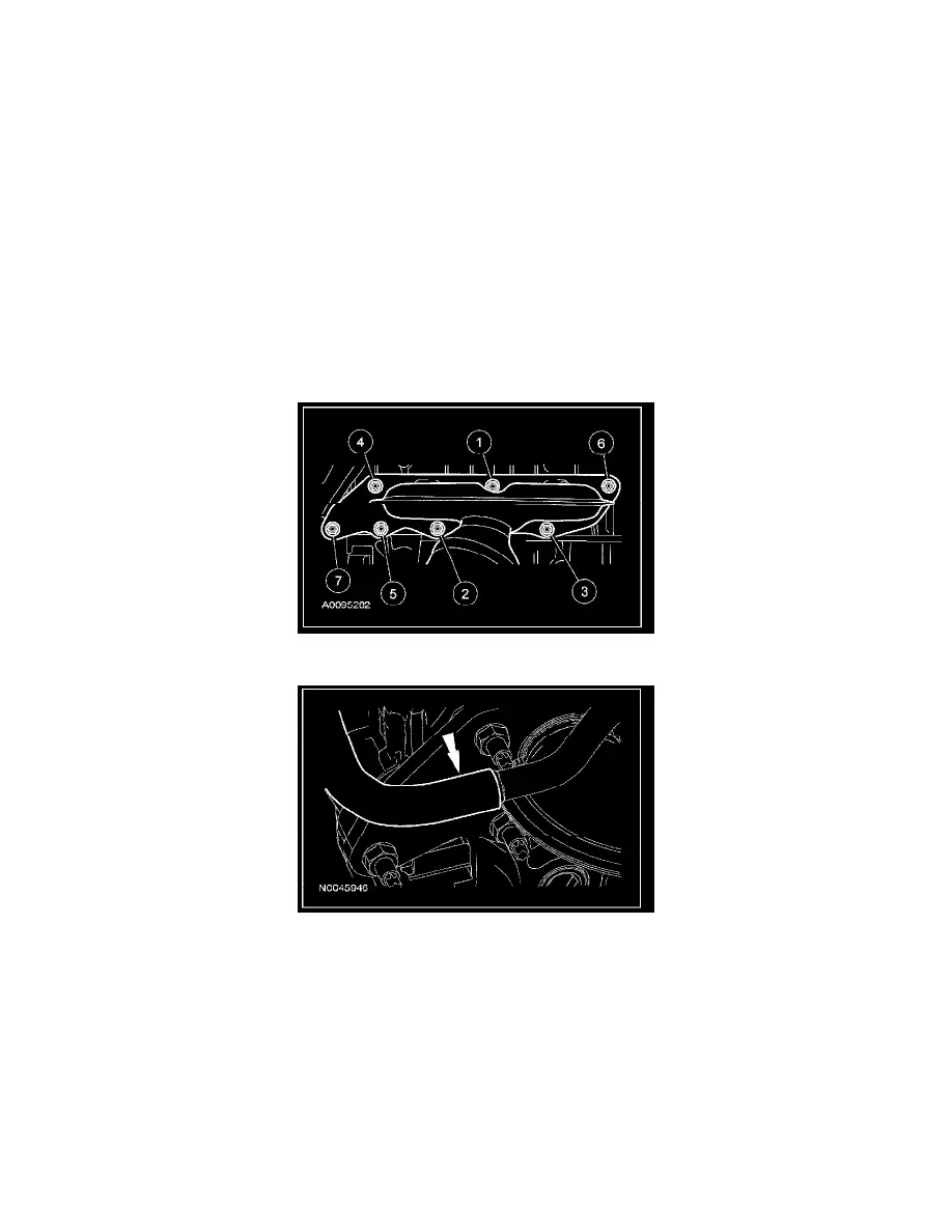
NOTE: Make sure to tighten the nuts in the following sequence in 2 stages.
Position the catalytic converter manifold and tighten the 7 new nuts in the sequence shown, in 2 stages.
^
Stage 1: Tighten to 55 Nm (41 lb-ft).
^
Stage 2: Tighten to 55 Nm (41 lb-ft).
4. Connect the secondary injection hose to the catalytic converter manifold.
5. Tighten the 2 catalytic converter manifold bracket bolts.
^
Tighten to 20 Nm (15 lb-ft).
6. Install the 2 catalytic converter manifold shield bracket bolts and the bracket.
^
Tighten to 20 Nm (15 lb-ft).
7. Position the heat shield and install the 4 heat shield bolts.
^
Tighten to 10 Nm (89 lb-inch).
8. Install the 2 catalytic converter manifold-to-exhaust flexible pipe nuts.
^
Install a new gasket and nuts.
^
Tighten to 40 Nm (30 lb-ft).
9. Position the wiring harness bracket on the stud.
10. Connect the HO2S and 2 catalyst monitor sensor electrical connectors.
11. Install the generator air inlet duct.