
Fusion AWD L4-2.3L (2008)
Front wheel drive (FWD) vehicles
3. Remove the wheel spindle. For additional information, refer to Wheel Spindle.
4. If equipped, detach the wheel speed sensor harness from the trailing arm.
5. Using a suitable jack, support the trailing arm.
6. WARNING: The coil spring is under extreme load. Care must be taken at all times when removing or installing a loaded spring. Failure
to follow this instruction may result in serious personal injury.
Remove and discard the lower arm outboard bolt.
^
To install, tighten to 103 Nm (76 lb-ft) with the suspension at the bushing fastener tightening position.
7. Remove and discard the upper arm outboard bolt.
^
To install, tighten to 110 Nm (81 lb-ft) with the suspension at the bushing fastener tightening position.
8. Carefully lower the trailing arm and remove the jack.
9. Remove and discard the shock absorber lower bolt and flagnut.
^
To install, tighten to 115 Nm (85 lb-ft) with the suspension at the bushing fastener tightening position.
10. Remove and discard the toe link outboard bolt.
^
To install, tighten to 110 Nm (81 lb-ft) with the suspension at the bushing fastener tightening position.
AWD vehicles
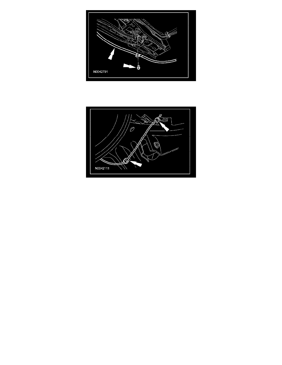
11. Remove the wheel speed sensor harness bracket nut and position aside the bracket.
^
To install, tighten to 23 Nm (17 lb-ft).
12. Remove the toe link. For additional information, refer to Toe Link.
13. Remove the 4 trailing arm-to knuckle nuts and the trailing arm toe link bracket.
^
Discard the nuts.
^
To install, tighten to 90 Nm (66 lb-ft).
All vehicles
14. Remove the 2 trailing arm-to-frame bolts, cone washers and the trailing arm.
^
Discard the nuts.
^
To install, tighten the bolts to 125 Nm (92 lb-ft).