
Fusion AWD V6-3.0L (2009)
Medium Speed Controller Area Network (MS-CAN) Operation
The MS-CAN communicates using bussed messages. The MS-CAN has an unshielded twisted pair cable, data bus (+) and data bus (-) circuits. In
addition to scan tool communication, this network allows sharing of information between all modules on the network.
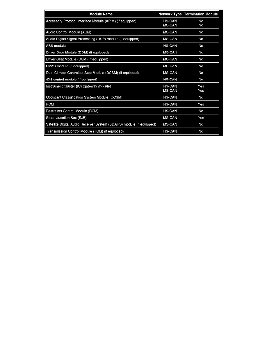
The MS-CAN is a medium speed communication network used for the following modules:
-
Accessory Protocol Interface Module (APIM) (if equipped)
-
Audio Control Module (ACM)
-
Audio Digital Signal Processing (DSP) module (if equipped)
-
Driver Door Module (DDM) (if equipped)
-
Driver Seat Module (DSM) (if equipped)
-
Dual Climate Controlled Seat Module (DCSM) (if equipped)
-
HVAC module
-
Instrument Cluster (IC)
-
Parking Aid Module (PAM)
-
Satellite Digital Audio Receiver System (SDARS) module (if equipped)
-
Smart Junction Box (SJB)
High Speed Controller Area Network (HS-CAN) Operation
The HS-CAN communicates using bussed messages. The HS-CAN uses an unshielded twisted pair cable, data bus (+) and data bus (-) circuits. In
addition to scan tool communication, this network allows sharing of information between all modules on the network.
The HS-CAN is a high speed communication network used for the following modules:
-
ABS module
-
APIM (if equipped)
-
IC
-
Occupant Classification System Module (OCSM)
-
PCM
-
Restraints Control Module (RCM)
-
Transmission Control Module (TCM) (if equipped)
-
4X4 control module (if equipped)
Network Termination
The CAN uses a network termination circuit to improve communication reliability. The network termination of the CAN bus takes place inside the
termination modules by termination resistors. Termination modules are located at either end of the bus network. As network messages are broadcast in