
Fusion AWD V6-3.0L (2009)
GO to T6.
No
GO to T9.
-------------------------------------------------
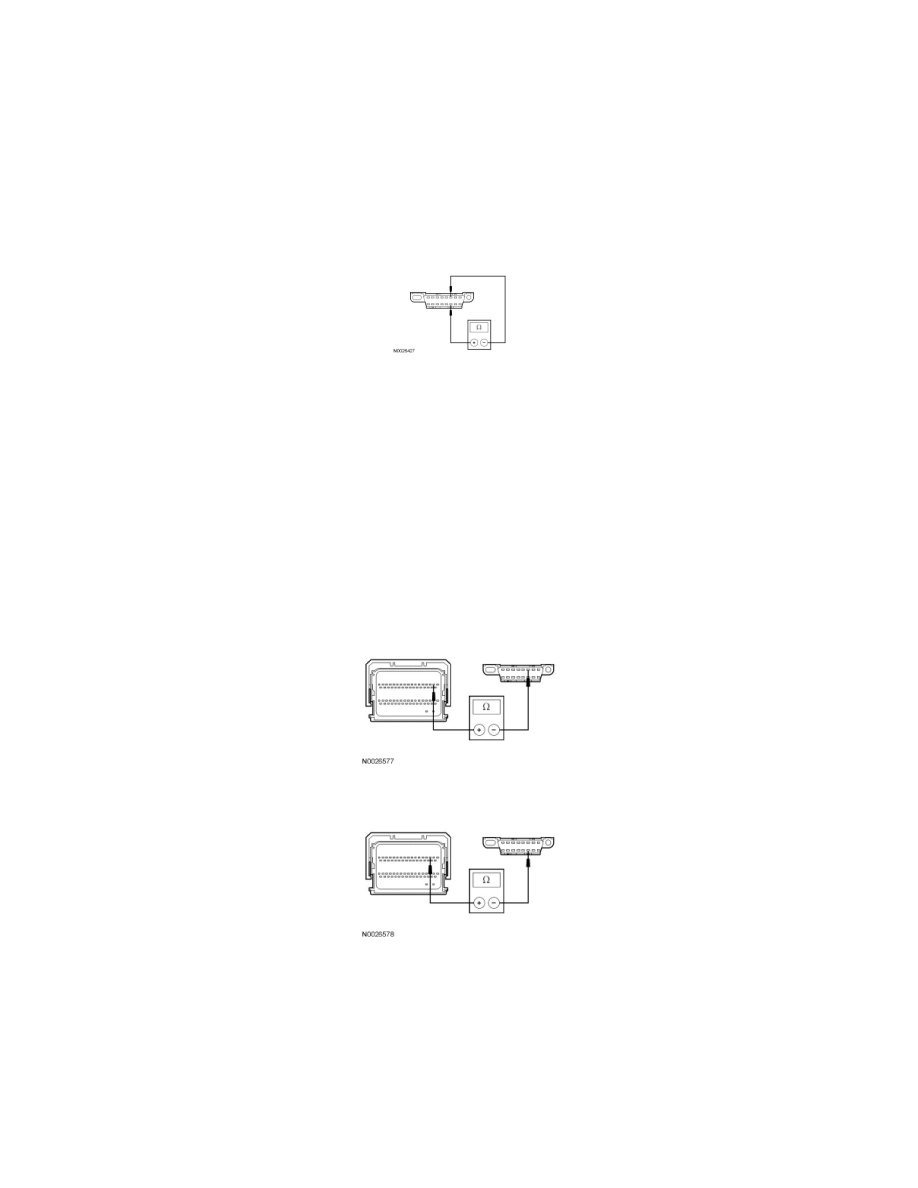
T6 CHECK THE HS-CAN TERMINATION RESISTOR WITH THE PCM DISCONNECTED
-
Disconnect: PCM C175b.
-
Measure the resistance between the DLC C251-6, circuit VDB04 (WH/BU), harness side and the DLC C251-14, circuit VDB05 (WH), harness
side.
-
Is the resistance between 108 and 132 ohms?
Yes
GO to T7.
No
GO to T8.
-------------------------------------------------
T7 CHECK THE HS-CAN CIRCUITS BETWEEN THE PCM AND THE DLC FOR AN OPEN
-
Measure the resistance between the PCM C175b-2, circuit VDB04 (WH/BU), harness side and the DLC C251-6, circuit VDB04 (WH/BU),
harness side.
-
Measure the resistance between the PCM C175b-3, circuit VDB05 (WH), harness side and the DLC C251-14, circuit VDB05 (WH), harness side.
-
Are the resistances less than 5 ohms?
Yes
CONNECT the negative battery cable. GO to T31.
No
REPAIR the circuit in question. CONNECT the negative battery cable. CLEAR the DTCs. REPEAT the network test with the scan tool.
-------------------------------------------------