
Fusion FWD L4-2.3L (2008)
14. CAUTION: Make sure that the manual valve is in the manual control valve shift lever.
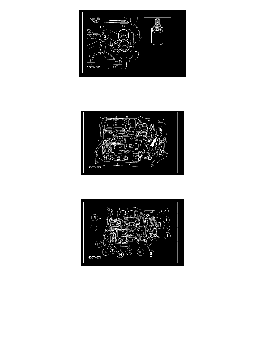
NOTE: Do not fully tighten the main control valve bolts at this stage.
Install the main control valve body and loosely install the bolts.
15. Tighten the main control valve body retaining bolts.
^
Tighten the bolts in the sequence shown.
-
Tighten to 9 Nm (80 lb-in).
16. NOTE: It is necessary to connect the electrical connectors in the same positions as noted in disassembly. Connector color letters are cast into the
solenoid body.
Install the main control valve wiring harness, connect the electrical connectors and install the ground wire bolt.
1
Solenoid SSA, color (BU/GN).
2
Solenoid SSB, color (BK/GN).
3
Solenoid SSC, color (BU/BN).
4
Solenoid PCA, color (BU/BN).
5
Solenoid SSD, color (WH).
6
Solenoid SSE, color (RD).
^
Tighten to 10 Nm (89 lb-in).