
Fusion FWD L4-2.3L VIN Z (2007)
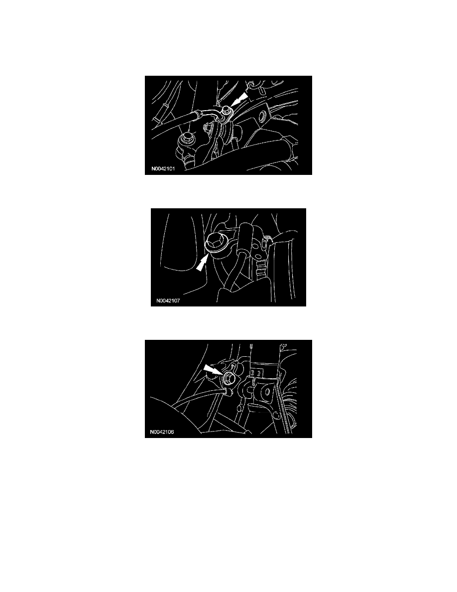
1. Remove and discard the 3 shock absorber upper mount nuts.
-
To install, tighten to 30 Nm (22 ft. lbs.).
2. With the vehicle in NEUTRAL, position it on a hoist.
3. Remove the brake line bracket bolt and position the brake line aside.
-
To install, tighten to 23 Nm (17 ft. lbs.).
4. If equipped, remove the wheel speed sensor bolt.
-
To install, tighten to 23 Nm (17 ft. lbs.).
5. If equipped, remove the wheel speed sensor harness bolt and position the wheel speed sensor aside.
-
To install, tighten to 23 Nm (17 ft. lbs.).
6. Using a suitable jack, support the wheel knuckle at the lower ball joints.
7. NOTE: Use the holding feature to prevent the ball stud from turning while removing or installing the stabilizer bar link nut.
Remove the stabilizer bar link upper nut.
-
To install, tighten to 40 Nm (30 ft. lbs.).
8. Remove the shock absorber lower bolt, flag nut and damper.
-
Discard the bolt and flag nut.
-
To install, tighten to 103 Nm (76 ft. lbs.) with the suspension at the bushing fastener tightening position.
9. Remove the shock absorber-to-damper fork bolt and separate the damper fork from the shock absorber and spring assembly.
-
To install, tighten to 48 Nm (35 ft. lbs.).
10. Lower the wheel knuckle and remove the shock absorber and spring assembly.
11. CAUTION: Before tightening any suspension bushing fasteners, the suspension must be at the bushing fastener tightening position. Use a suitable
jack to raise the suspension until the distance between the center of the hub and the lip of the fender is equal to 402 mm (15.83 inch).