
Fusion FWD V6-3.0L (2009)
-------------------------------------------------
B1 CHECK THE TCM VOLTAGE SUPPLY CIRCUITS FOR AN OPEN
-
Ignition OFF.
-
Disconnect: TCM C2352a (FNR5 Transaxle).
-
Disconnect: TCM C1533 (6-Speed Transaxle).
-
Ignition ON.
-
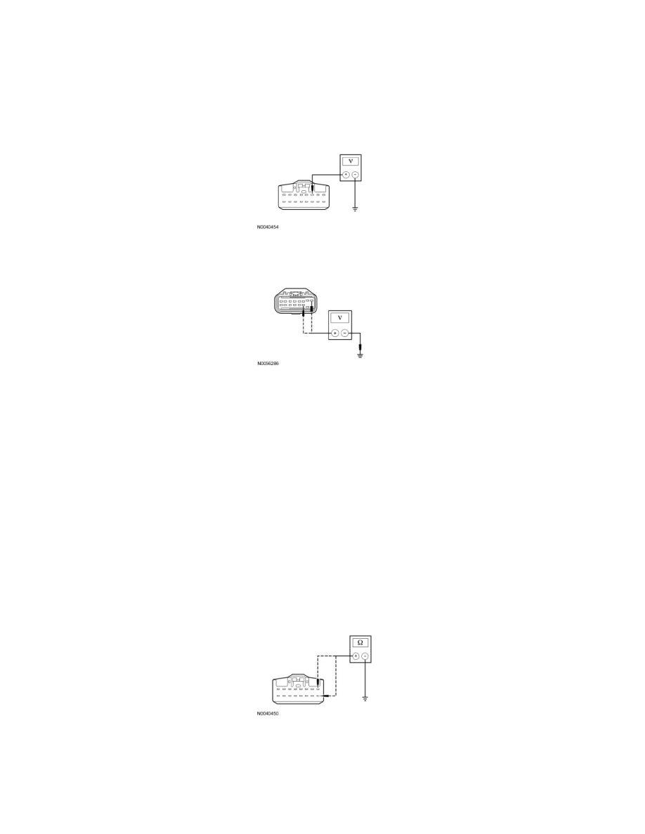
For FNR5 transaxles, measure the voltage between the TCM C2352a-3, circuit SBP23 (WH/RD), harness side and ground.
-
For 6-speed transaxles, measure the voltage between the TCM C1533-1, circuit SBB16 (VT/RD), harness side and ground; and between the TCM
C1533-11, circuit CBP18 (GY/OG), harness side and ground.
-
Are the voltages greater than 10 volts?
Yes
GO to B2.
No
For FNR5 transaxles, VERIFY the Battery Junction Box (BJB) fuse 23 (10A) is OK.
For 6-speed transaxles, VERIFY the BJB fuse 16 (15A) or Smart Junction Box (SJB) fuse 26 (7.5A) is OK. If OK, REPAIR the circuit in question.
CLEAR the DTCs. REPEAT the network test with the scan tool.
-------------------------------------------------
B2 CHECK THE TCM GROUND CIRCUITS FOR AN OPEN
-
Ignition OFF.
-
Disconnect: Negative Battery Cable.
-
For FNR5 transaxles, measure the resistance between the TCM C2352a-1, circuit GD120 (BK/GN), harness side and ground; and between the
TCM C2352a-9, circuit GD120 (BK/GN), harness side and ground.
-
For 6-speed transaxles, measure the resistance between TCM C1533-9, circuit GD120 (BK/GN), harness side and ground.