
Fusion FWD V6-3.0L (2009)
-
Is the resistance less than 5 ohms?
Yes
GO to K3.
No
REPAIR the circuit. CONNECT the negative battery cable. CLEAR the DTCs. REPEAT the network test with the scan tool.
-------------------------------------------------
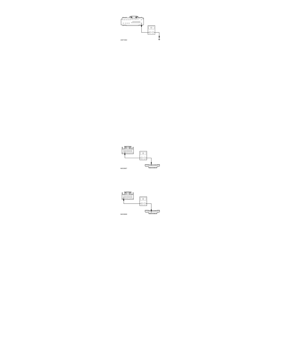
K3 CHECK THE MS-CAN CIRCUITS BETWEEN THE ACM AND THE DLC FOR AN OPEN
-
Ignition OFF.
-
Disconnect: ACM C290c (Base Audio/Audiophile) or C240c (THX(R) Audio/Navigation).
-
Measure the resistance between the ACM C290c-15 (base audio/Audiophile) or the audio Digital Signal Processing (DSP) module C240c-15
(THX(R) audio/navigation), circuit VDB06 (GY/OG), harness side and the Data Link Connector (DLC) C251-3, circuit VDB06 (GY/OG),
harness side.
-
Measure the resistance between the ACM C290c-16 (base audio/Audiophile) or the audio DSP module ACM C240c-16 (THX(R)
audio/navigation), circuit VDB07 (VT/OG), harness side and the DLC C251-11, circuit VDB07 (VT/OG), harness side.
-
Are the resistances less than 5 ohms?
Yes
CONNECT the negative battery cable. GO to K4.
No
REPAIR the circuit in question. CONNECT the negative battery cable. CLEAR the DTCs. REPEAT the network test with the scan tool.
-------------------------------------------------
K4 CHECK FOR CORRECT ACM OPERATION
-
Disconnect all the ACM connectors.
-
Check for:
-
corrosion
-
damaged pins
-
pushed-out pins
-
Connect all the ACM connectors and make sure they seat correctly.
-
Operate the system and verify the concern is still present.
-
Is the concern still present?
Yes
INSTALL a new ACM. REFER to Radio, Stereo and Compact Disc. TEST the system for normal operation.