
Fusion FWD V6-3.0L (2009)
-
Are DLC pins 3 and 11 OK?
Yes
GO to S2.
No
REPAIR the DLC as necessary. CLEAR the DTCs. REPEAT the network test with the scan tool.
-------------------------------------------------
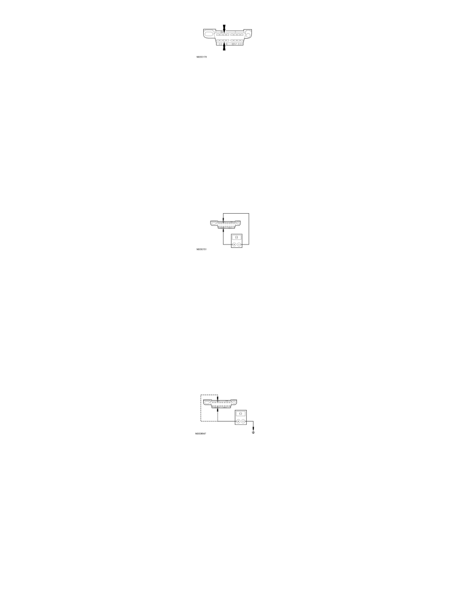
S2 CHECK THE MS-CAN TERMINATION RESISTANCE
-
Disconnect: Negative Battery Cable.
-
Measure the resistance between the DLC C251-3, circuit VDB06 (GY/OG), harness side and the DLC C251-11, circuit VDB07 (VT/OG), harness
side.
-
Is the resistance between 54 and 66 ohms?
Yes
GO to S3.
No
Go To Pinpoint Test Q.
-------------------------------------------------
S3 CHECK THE MS-CAN (+) AND MS-CAN (-) CIRCUITS FOR A SHORT TO GROUND
-
Measure the resistance between the DLC C251-3, circuit VDB06 (GY/OG), harness side and ground; and between the DLC C251-11, circuit
VDB07 (VT/OG), harness side and ground.
-
Are the resistances greater than 1,000 ohms?
Yes
GO to S4.
No
Go To Pinpoint Test Q.
-------------------------------------------------
S4 CHECK THE MS-CAN (+) AND MS-CAN (-) CIRCUITS FOR A SHORT TO VOLTAGE
-
Connect: Negative Battery Cable.
-
Ignition ON.