
Fusion FWD V6-3.0L (2009)
NOTE: Failure to disconnect the battery when instructed will result in false resistance readings. Refer to Battery.
-------------------------------------------------
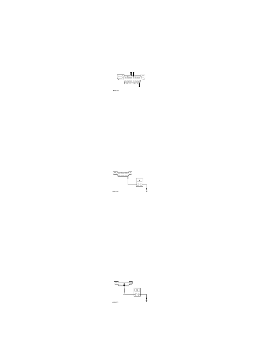
V1 CHECK THE DLC PINS FOR DAMAGE
NOTE: Most faults are due to connector and/or wiring concerns. Carry out a thorough inspection and verification before proceeding with the pinpoint
test.
-
Disconnect the scan tool cable from the DLC.
-
Inspect DLC pins 4, 5 and 16 for damage.
-
Are DLC pins 4, 5 and 16 OK?
Yes
GO to V2.
No
REPAIR the DLC as necessary. CLEAR the DTCs. REPEAT the network test with the scan tool.
-------------------------------------------------
V2 CHECK THE DLC VOLTAGE SUPPLY FOR AN OPEN
-
Measure the voltage between the DLC C251-16, circuit SBP11 (BU/RD), harness side and ground.
-
Is the voltage greater than 10 volts?
Yes
GO to V3.
No
VERIFY the Smart Junction Box (SJB) fuse 18 (20A) is OK. If OK, REPAIR the circuit. REPEAT the network test with the scan tool.
-------------------------------------------------
V3 CHECK THE DLC GROUND CIRCUITS FOR AN OPEN
-
Disconnect: Negative Battery Cable.
-
Measure the resistance between the DLC C251-4, circuit GD116 (BK/VT), harness side and ground; and between the DLC C251-5, circuit GD116
(BK/VT), harness side and ground.
-
Are the resistances less than 5 ohms?
Yes