
Fusion FWD V6-3.0L (2009)
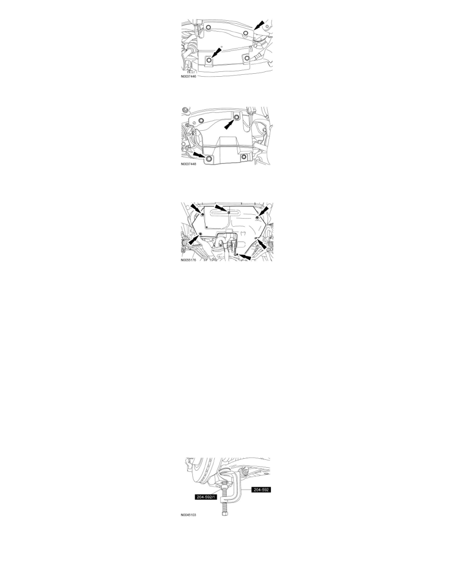
8. Remove the 6 pin-type retainers (4 shown) and the LH splash shield.
9. If equipped, remove the 7 screws and the underbody cover shield.
-
To install, tighten 7 Nm (62 lb-in).
10. Remove and discard the 2 catalytic converter manifold-to-exhaust flexible pipe nuts and separate the exhaust flexible pipe.
-
To install, tighten the new nuts to 40 Nm (30 lb-ft).
11. Using 2 suitable jack stands, support the rear of the subframe assembly.
12. Remove and discard the 4 subframe bracket-to-body bolts, the 2 subframe bracket-to-subframe nuts and washers. Lower the rear of the subframe.
-
To install, tighten the new bolts to 103 Nm (76 lb-ft).
-
To install, tighten the new nuts to 150 Nm (111 lb-ft).
13. Remove and discard the rear lower ball joint nut.
-
To install, tighten the new nut to 200 Nm (148 lb-ft).
14. NOTICE: When the lower ball joint is separated from the wheel knuckle, the lower arm may strike the outer Constant Velocity (CV)
joint boot with enough force to damage the boot clamp. This will result in a loss of grease from the outer CV joint. Place a block of wood,
or similar item, between the lower arm and the outer CV joint to prevent the lower arm from striking the outer CV joint.
NOTE: Once pressure is applied to the ball joint with the Ball Joint Separator and Adapter, it may be necessary to tap the wheel knuckle at the
ball joint area to separate the ball joint from the wheel knuckle.
Using the Ball Joint Separator and Adapter, separate the rear lower ball joint from the wheel knuckle.
15. Remove the rear lower arm-to-subframe bolt and washer and remove the rear lower arm.
-
Discard the bolt and washer.
-
To install, tighten the new bolt to 65 Nm (48 lb-ft), then tighten an additional 90 degrees.