
Fusion FWD V6-3.0L (2009)
Differential Assembly: Description and Operation
Driveline System
Driveline System
The driveline system consists of the following components:
-
Center support bearing
-
Driveshaft assembly
-
Front halfshafts
-
Rear halfshafts
-
Active torque coupling/rear axle
On Front Wheel Drive (FWD) vehicles, the transaxle transmits power from the engine to the halfshafts.
On All-Wheel Drive (AWD) vehicles, power is transmitted from the engine through the transaxle to the Power Transfer Unit (PTU). The PTU transfers
engine power from the transaxle to the front halfshafts, and through the driveshaft to the active torque coupling/rear axle and halfshafts.
The engine angle is built into the engine mounts. If the engine angle is out of specification, the engine mounts must be inspected for damage.
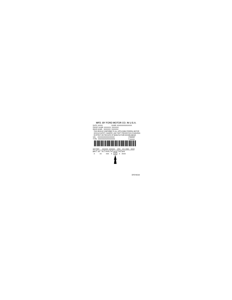
Vehicle Certification (VC) Label Example
The Vehicle Certification (VC) label is located in the driver door jamb. The axle code is on the VC label. Refer to Vehicle/Application ID.
The axle ratio is 2.93 and the ring gear has a diameter of 174 mm (6.85 in).
The wheel speed sensor rings for FWD vehicles are located on the front halfshafts and are mounted to the rear inner spindles.
The wheel speed sensor rings are located on the front and rear halfshafts for AWD vehicles.
Driveshaft
The driveshaft is a 3-piece shaft with rubber-isolated center bearings.
The driveshaft has traditional balance weights attached (spot-welded) by the manufacturer.
U-joints
The CV and U-joints are installed new with the driveshaft.
The front CV joint is:
-
lubricated with a special lubricant and requires no additional lubrication.
The center U-joints are:
-
a lubed-for-life design that requires no periodic lubrication.