| In-vehicle Repair Special Tool(s) | | Flange holding wrench, universal 205-072 (15-030 A) | | | Angle gauge, bolt tightening 303-174 (21-540) | | | Support bar, engine 303-290A (21-140A) | | | Adapter for 303-290A 303-290-02 (21-140-02) | | | Adapter for 303-290A 303-290-04A (21-140-04A) | | | Adapter for 303-290A 303-290-07 (21-140-07) | | | Adapters for 303-338 (studs) 303-338-01 (21-153-01) | | | Remover, vibration damper hub 303-509 (21-213) | | | Installer, crankshaft vibration damper 303-510 (21-214) | General Equipment 2.5 mm drill bit Brass drift Materials Name Specification Engine oil WSS-M2C913–A or WSS-M2C912–A1 Silicon grease A960-M1C171-AA High-temperature grease ESDM-M1C220-A Removal | | -
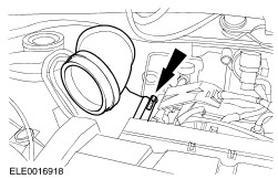
Remove the air cleaner outlet pipe body. | | | -
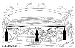
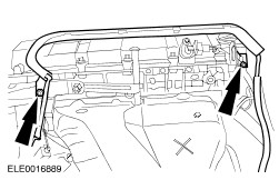
Remove the bulkhead cover. | | | -
Remove the spark plug cover. | | | -
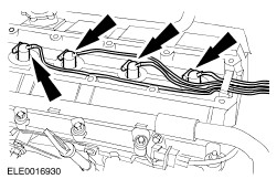
Disconnect the spark plug wires from the spark plugs. | | | -
Detach the generator wiring harness support guide from the cylinder head. | | | -
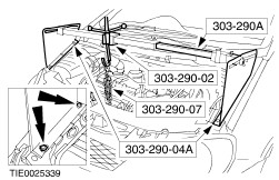
Install the special tools. | | | -
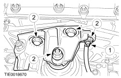
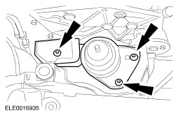
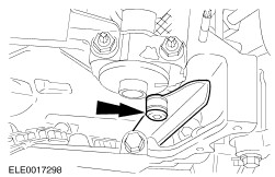
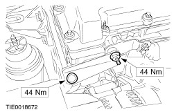
Remove the engine front mounting bracket and disconnect the ground cable from the mounting bracket. - Disconnect the ground cable from the engine front mounting bracket.
- Remove the engine front mounting bracket nuts and bolts.
| | | -
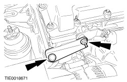
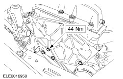
Remove the engine support plate bracket. | | | -
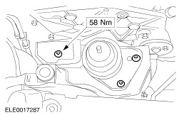
Remove the engine front mounting. | | | -
Remove the engine lower support plate retaining bolts together with the engine support plate. | | | -
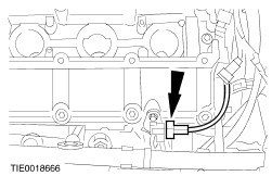
Disconnect the camshaft position (CMP) sensor electrical connector. | | | -
Remove the upper front cover. | | | -
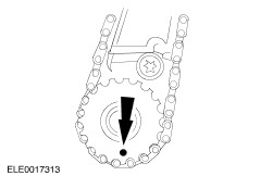
Rotate the crankshaft in its normal direction until piston No. 1 is on top dead center. | | | -
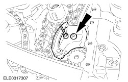
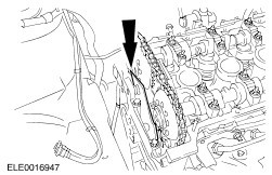
Remove the timing chain upper guide. - Discard the timing chain upper guide.
| | | -
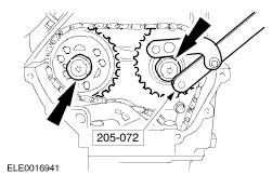
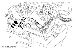
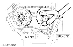
Using the special tool, remove the camshaft sprockets. | | | -
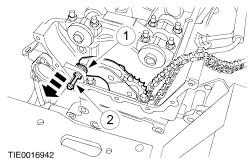
CAUTION:Prevent the retaining washer from dropping into the timing case. NOTE:Using a suitable piece of wire prevent the timing chain from dropping into the timing case. Remove the timing chain tensioner. - Remove the retaining washer.
- Using a M6 x 60 bolt, remove the timing chain tensioner pivot bolt.
| | | -
Remove the timing chain tensioner. - Discard the timing chain tensioner.
| | | -
Remove the lower front cover retaining bolts. | | | -
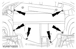
Remove the engine undershield (two nuts and four bolts). | | | -
Drain the engine oil. - Discard the oil drain plug washer.
| | | -
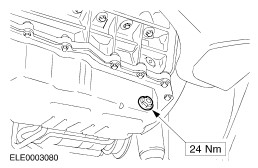
NOTE:Install a new oil drain plug washer. Install the oil drain plug. | | | -
Remove the accessory drive belt. For additional information, refer to Section 305-05 . | | | -
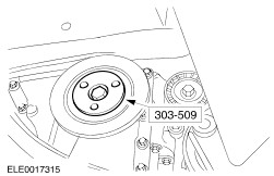
Using three M8 x 25 bolts, attach the special tool to the crankshaft pulley. - Apply grease on the mating face of the special tool and the crankshaft pulley retaining bolt.
| | | -
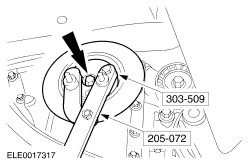
Using the special tool, remove the crankshaft pulley. - Using two M8 x 30 bolts, install the special tool.
| | | -
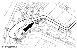
Detach the power steering line from the engine. | | | -
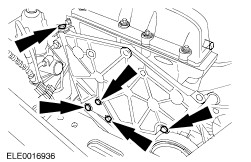
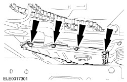
Remove the lower front cover (12 bolts). | | | -
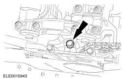
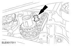
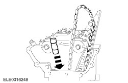
CAUTION:Wrap the flutes of the drill bit with a suitable tape. Failure to follow this instruction may result in personal injury. Remove the oil pump chain tensioner. - Tension the oil pump chain tensioner, lock it in position with a 2.5 mm drill bit and remove it.
| | | -
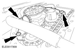
Remove the oil pump chain guides. | | | -
Remove the oil pump chain. | | | -
Remove the timing chain guide lower retaining bolt. | | | -
Remove the timing chain guide upper retaining bolt. | | | -
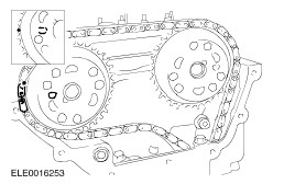
Remove the timing chain and the timing chain guide. | Installation | | -
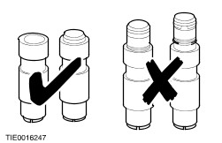
CAUTION:Fully or partially released timing chain tensioners must not be used (whether new or used). Check the new timing chain tensioner. | | | -
CAUTION:Install a new timing chain tensioner. Install the timing chain tensioner. | | | -
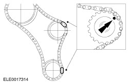
NOTE:The single copper colored link must be at the lower end of the chain guide. Install the timing chain and the timing chain guide. - Using a suitable piece of wire, prevent the timing chain from dropping into the timing case.
| | | -
Install the timing chain guide upper retaining bolt. | | | -
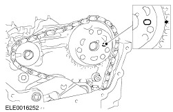
NOTE:The copper link of the timing chain must align with the timing marks on the crankshaft timing sprocket. Install the timing chain. | | | -
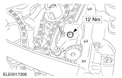
Tighten the timing chain guide lower retaining bolt. | | | -
CAUTION:Prevent the retaining washer from dropping into the timing case. Install the timing chain tensioner. - Using a M6 x 60 bolt, install the timing chain tensioner pivot bolt.
- Install the retaining washer.
| | | -
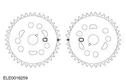
CAUTION:The camshaft sprockets must locate in the slots on the camshaft. NOTE:The copper links of the timing chain must align with the timing marks on the camshaft sprocket. NOTE:The timing chain must be taut on the long side. Install the exhaust camshaft sprocket and the timing chain. - If necessary rotate the camshaft slightly.
| | | -
NOTE:The copper links of the timing chain must align with the timing marks on the camshaft sprockets. NOTE:The timing chain may hang down slightly between the camshaft sprockets. Install the inlet camshaft sprocket and the timing chain. | | | -
Tighten both camshaft sprocket retaining bolts finger tight. | | | -
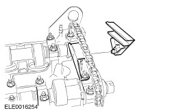
Using a suitable brass drift, release the timing chain tensioner. | | | -
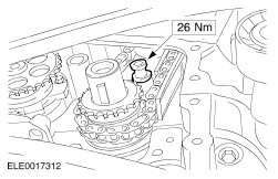
Using the special tool, tighten the camshaft sprocket retaining bolts. | | | -
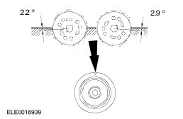
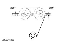
Rotate the crankshaft in its normal direction until piston No. 2 is on TDC. - Make sure the marks on the camshaft sprockets face one another exactly on level with the upper edge of the cylinder head.
| | | -
CAUTION:If the timing chain had to be removed while adjusting the valve timing, a new timing chain tensioner must be installed. Check the valve timing. - Rotate the crankshaft one revolution in its normal direction and set it to the marks.
| | | -
NOTE:Install a new timing chain upper guide. Install the timing chain upper guide. | | | -
NOTE:Make sure piston No. 2 is on TDC. NOTE:The copper link of the timing chain must align with the timing marks on the crankshaft timing sprocket and on the balancer shaft sprocket. Install the oil pump chain. | | | -
Install the oil pump chain guides. | | | -
WARNING:Wrap the flutes of the drill bit with a suitable tape. Failure to follow this instruction may result in personal injury. Install the oil pump chain tensioner. - Install the oil pump chain tensioner retaining bolt.
| | | -
NOTE:A new lower front cover is supplied with an alignment sleeve that must be removed following installation. Install the lower front cover (12 bolts). | | | -
Remove the alignment sleeve. | | | -
Attach the power steering line to the engine. | | | -
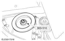
Using the special tool, install the crankshaft pulley. | | | -
Using three M8 x 25 bolts, attach the special tool to the crankshaft pulley. | | | -
Using the special tools and two M8 x 30 bolts,, tighten the crankshaft pulley retaining bolt. - Tighten the bolt in two stages.
| | | -
Install the accessory drive belt. For additional information, refer to Section 305-05 . | | | -
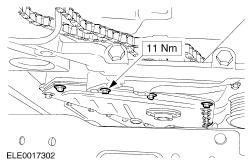
Install the lower front cover retaining bolts (four bolts). | | | -
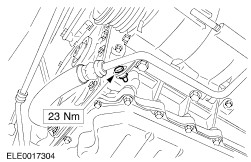
NOTE:Install a new gasket. NOTE:Align the upper edge of the upper cover with the cylinder head mating face (maximum downward offset = 0.13 mm) Install the upper front cover. | | | -
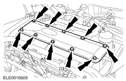
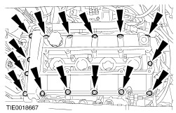
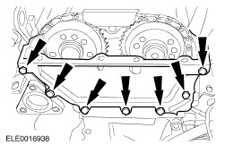
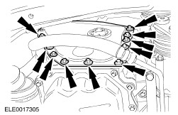
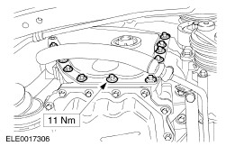
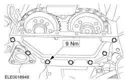
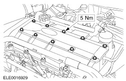
NOTE:Install a new gasket. Install the valve cover (4 nuts and 11 bolts). - Tighten the nuts bolts in the sequence shown in two stages.
- Stage 1: Tighten nuts and bolts 1 through 15 to 3 Nm.
- Stage 2: Tighten nuts and bolts 1 through 15 to 9 Nm.
| | | -
Connect the CMP sensor electrical connector. | | | -
Install the engine support plate. | | | -
Install the engine front mounting. | | | -
Install the engine support plate bracket. | | | -
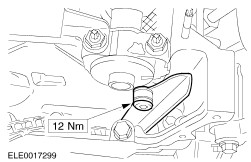
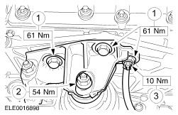
Install the engine front mounting bracket and connect the ground cable to the mounting bracket. - Install the bolts.
- Install the nut.
- Connect the ground cable.
| | | -
Remove the special tools. | | | -
Attach the generator wiring harness support guide to the cylinder head. | | | -
Using a suitable blunt object to avoid damage to the spark plug connector gasket, coat the inside of the spark plug connector with silicone grease to a depth of 5-10 mm. | | | -
CAUTION:Connect the spark plug wires in line with the spark plugs. Connect the spark plug wires to the spark plugs. | | | -
Install the spark plug cover. | | | -
Install the bulkhead cover. | | | -
Install the air cleaner outlet pipe. | | | -
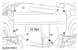
Install the engine undershield (two nuts and four bolts). | | |