| Disassembly and Assembly Special Tool(s) | | Boot clamp tightening tool 204-169 (14-044) | | | Separating tool 205-310 (15-091) | | | Bridge, drive pinion bearing remover 205-311 (15-092) | General Equipment Materials Name Specification High-durability grease WSD-M1C230-A Disassembly | | -
NOTE:Use protective covers. Loosen the clamping straps from the boot. - Detach the front drive halfshaft from the intermediate shaft.
- Clamp the intermediate shaft in a vice.
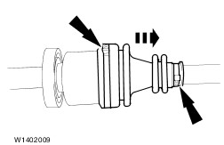
- Separate and discard the clamping straps. Push back the boot.
| | | -
CAUTION:Constant velocity rollers can drop out. Separate the tripode joint. - Remove the grease from inside the joint.
| | | -
Dismantle the tripode assembly - Remove the rollers.
- Detach the snap-ring.
| | | -
Pull off the tripode assembly | | | -
CAUTION:Do not damage the bearing cage. Release the constant velocity joint at the wheel end. - Separate and discard the clamping straps. Push back the boot.
- Release the constant velocity joint from the snap-ring seat using a brass drift.
| | | -
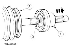
Detach the constant velocity joint. - Pull off the constant velocity joint.
- Detach the snap-ring.
- Pull off the boot.
| | | -
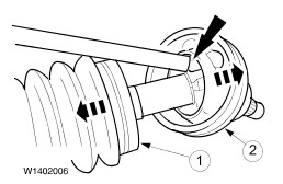
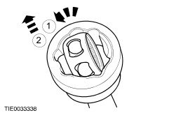
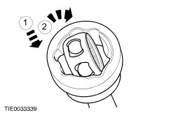
Detach the bearing cage and bearing star from the bearing shell. - Turn the bearing cage together with the bearing star.
- Pull the bearing cage with the bearing star out of the bearing shell.
| | | -
Remove the balls from the bearing cage. | | | -
NOTE:Make sure that the bearing housing, cage, balls and star are free of grease and oil. Check all running surfaces for wear. | | | -
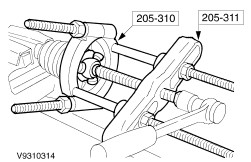
Press off the centre bearing. | Assembly | | -
General note. - Renew all snap-rings and clamping straps.
| | | -
Press on the centre bearing. | | | -
Fit the boot at the transmission end. - Slide on the boot with the inner clamping strap.
- Locate the boot in position.
| | | -
Insert the clamping strap in the groove of the boot and tighten with the special tool. | | | -
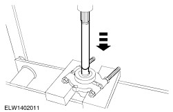
CAUTION:Do not damage the bearing seat of the rollers. Fit the tripode star. - Drive the tripode star onto the front drive halfshaft as far as it will go, using a suitable tube.
| | | -
NOTE:Use a new snap-ring. Assemble the tripode joint. - Snap-ring
- Fit the constant velocity rollers, applying high-durability grease.
| | | -
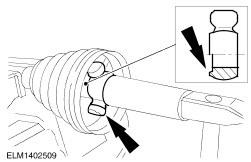
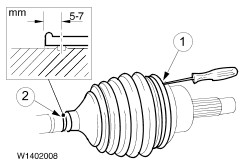
Attach the intermediate shaft to the front drive halfshaft. - Slide a small screwdriver under the boot seat to allow the air to escape.
- Slide the tripode joint inwards as far as the stop, then pull it out 20 mm.
| | | -
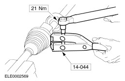
Insert the clamping strap in the groove of the sleeve and tighten with the special tool. | | | -
Install the balls in the bearing cage. | | | -
Install the bearing cage with bearing star in the bearing shell. - Slide the bearing cage with bearing star into the bearing shell.
- Turn the bearing cage together with the bearing star.
| | | -
NOTE:Use a new snap-ring. Make sure the circlip clicks into place. Install the constant velocity joint at the wheel end. - Slide on the boot with the inner clamping strap.
- Fit the snap-ring.
- Fill the constant velocity joint with 80 grammes of high-durability grease and push onto the driveshaft.
| | | -
Fit the boot. - Press the boot into the groove on the driveshaft.
- Slide a small screwdriver under the boot seat to allow the air to escape.
- Locate the boot in position and remove the screwdriver.
- Tension the clamping straps (see previous step).
| | |