| Diagnosis and Testing Refer to Wiring Diagrams Section 501-20B, for schematic and connector information. Special Tool(s) | | Simulator, Air Bag - Driver and Passenger 418-037 (40-001) | | | Test and Deployment Lead, Air Bag 418-S055C (40-007) | | | Simulator, Side Air Bag 501-075 (40-018) | General Equipment Worldwide Diagnostic System (WDS) Diagnosing Customer Concerns Without Hard DTCs/LFCs WARNING:To avoid accidental deployment, the air bag control module backup power supply must be depleted. Wait at least one minute after disconnecting the battery ground cable(s) before commencing any repair or adjustment to the supplemental restraint system (SRS), or any component(s) adjacent to the SRS sensors. Failure to follow these instructions may result in personal injury. NOTE:Following the pinpoint tests when a diagnostic trouble code/lamp fault code (DTC/LFC) is not present, or the air bag warning indicator is not permanently illuminated, will result in needless replacement of air bag system components and repeat repairs. Speak with the customer to determine if a particular set of conditions must be met in order to indicate a fault. If a LFC is reported by the customer but is not present when the vehicle comes in for repair, pinpoint test diagnostics cannot be used. Instruct the customer on how to count a LFC. Diagnosing Customer Concerns with Hard DTCs/LFCs WARNING:Do not use substitute air bag simulators when working on the SRS. Use only the appropriate tool. Failure to follow these instructions may result in personal injury. Most air bag system diagnostic procedures require the use of system deactivation and system reactivation procedures. These procedures require the air bag module(s) to be disconnected from the SRS, thereby removing the risk of the air bag deployment while diagnostics are carried out. Air bag simulators are required to carry out diagnosis and testing of the air bag system. It is not acceptable to short-circuit the air bag module connections with a 0 ohm jumper wire. If a 0 ohm jumper wire is used to short-circuit the air bag module connections, a LFC will be displayed and a DTC logged by the air bag control module. Deactivation WARNING:The backup power supply must be depleted, before any work is carried out on the SRS. Wait at least one minute after disconnecting the battery ground cable before disconnecting any SRS electrical connector. Failure to follow this instruction may result in personal injury. - Disconnect the battery ground cable.
REFER to: Battery Disconnect and Connect (414-01 Battery, Mounting and Cables, General Procedures).
- Wait at least one minute for the backup power supply in the air bag control module to deplete its stored energy.
WARNING:Place the air bag module(s) on a ground wired bench, with the trim cover facing up to avoid accidental deployment. Failure to follow this instruction may result in personal injury. - Remove the driver air bag module from the vehicle.
REFER to: Driver Air Bag Module (501-20B Supplemental Restraint System, Removal and Installation).
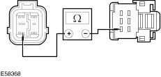
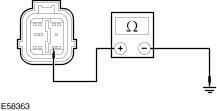
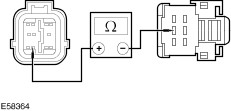
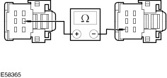
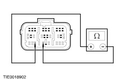
- Connect the driver air bag simulator to the sub-harness in place of the driver air bag module at the top of the steering column.
- Disconnect the passenger air bag module electrical connector.
REFER to: Passenger Air Bag Module (501-20B Supplemental Restraint System, Removal and Installation).
- Connect the passenger air bag simulator to the harness in place of the passenger air bag module.
- Disconnect the driver side underseat floor harness electrical connector (if equipped).
- Connect the driver side, side air bag simulator to the driver side underseat floor harness in place of the side air bag module (if equipped).
- Disconnect the passenger side underseat floor harness electrical connector (if equipped).
- Connect the passenger side, side air bag simulator to the passenger side underseat floor harness in place of the side air bag module (if equipped).
- Connect the battery ground cable.
REFER to: Battery Disconnect and Connect (414-01 Battery, Mounting and Cables, General Procedures).
Reactivation WARNING:The air bag simulators must be removed and the air bag module(s) reconnected when reactivated to avoid non-deployment in a collision. Failure to follow this instruction may result in personal injury. - Disconnect the battery ground cable.
REFER to: Battery Disconnect and Connect (414-01 Battery, Mounting and Cables, General Procedures).
- Wait at least one minute for the backup power supply in the air bag control module to deplete its stored energy.
- Remove the driver air bag simulator from the sub-harness at the top of the steering column.
- Connect and install the driver air bag module.
REFER to: Driver Air Bag Module (501-20B Supplemental Restraint System, Removal and Installation).
- Remove the passenger air bag simulator from the passenger air bag module harness.
- Connect and install the passenger air bag module.
REFER to: Passenger Air Bag Module (501-20B Supplemental Restraint System, Removal and Installation).
- Remove the driver side, side air bag simulator from the driver side underseat floor harness electrical connector (if equipped).
- Connect the driver side, side air bag module underseat floor harness electrical connector (if equipped).
- Remove the passenger side, side air bag simulator from the passenger side underseat floor harness electrical connector (if equipped).
- Connect the passenger side, side air bag module underseat floor harness electrical connector (if equipped).
- Connect the battery ground cable.
REFER to: Battery Disconnect and Connect (414-01 Battery, Mounting and Cables, General Procedures).
Glossary Air Bag Simulator Air bag simulators are used to simulate air bag module connections to the system. Deactivate The System Deactivate the system means to carry out deactivation. REFER to Deactivation in this procedure. Prove Out The System The air bag warning indicator will illuminate for approximately three seconds. If there is a fault condition, after a two second delay, the air bag warning indicator will: - illuminate continuously
- flash
Reactivate The System Reactivate the system means to carry out reactivation. REFER to Reactivation in this procedure. Principles of Operation SRS Operation The SRS is AC fired, with side impact sensors for vehicles equipped with side air bags. In the event of a severe frontal or three-quarter frontal impact, in excess of a predetermined limit, the driver and passenger (if equipped) front air bag(s) will deploy. In the event of a severe full side impact, in excess of a predetermined limit, either the driver or passenger side air bag will deploy. Air bag deployment will only occur, in the event of a severe collision when the ignition key is in the RUN position. The passenger air bag deactivation (PAD) switch (if equipped) will deactivate the passenger air bag in the event of a severe frontal or side impact; it will not deactivate the passenger side air bag or passenger safety belt buckle pretensioner. Air Bag Control Module The air bag control module is mounted horizontally to the floor pan beneath the floor console, to facilitate impact sensing along the longitudinal axis. The air bag control module retains full control of the whole system, providing continual system checks and full diagnostic capabilities. The non-volatile memory stores the fault codes, which can then be downloaded through the data link connector (DLC) to WDS. A visual warning indicator which is housed within the instrument cluster, is illuminated when the ignition is switched ON for approximately three seconds then goes out. If a fault occurs the warning indicator, depending on the nature of the fault, begins to flash or illuminates continuously after five seconds. In the event of a failure in the vehicle power supply during or after an accident, the air bag control module provides a backup power supply, sufficient to deploy the air bag(s) for a minimum of 150 ms. The backup power supply is discharged by the air bag control module within 60 seconds of the battery ground cable being disconnected. Thus making sure the SRS remains operational. The air bag control module contains a micro-controller to evaluate and process impact data and two micromachine sensors. An electronic accelerometer, which converts the actual acceleration and deceleration force, along the vehicles longitudinal axis into electrical signals. When both these sensors sense an impact, in excess of a predetermined limit, the air bag control module initiates the circuit to deploy the frontal air bags. The two micromachine sensors prevent unintentional deployment of the frontal air bags. Side Impact Sensor The side impact sensors are mounted either side of the vehicle, to facilitate remote lateral impact sensing. Each side impact sensor contains a micromachine which processes signals from an accelerometer within the sensor. In the event of an impact, in excess of a predetermined limit, the side impact sensor will process the side impact data, and initiate a deployment request to the air bag control module. The air bag control module processes this request against stored data, to deploy the side air bag on the side the deployment request was initiated. The air bag control module retains control of the side air bags. Air Bag Warning Indicator The air bag warning indicator is incorporated into the instrument cluster, together with the automatic detach detect circuit, the air bag warning indicator comes on for three seconds at key ON. If the system self-tests OK the indicator goes out, if a fault is detected the indicator will flash after five seconds, illuminate continually from key ON or not illuminate at all, depending on the nature of the fault. The automatic detach detect circuit is designed to illuminate the air bag warning indicator continuously, if the air bag control module circuit is broken, either by loss of power or ground supply. The air bag control module retaining bolts are part of the ground circuit. Diagnostic evaluation of the SRS can be made through the DLC and WDS to establish the nature of the concern. Inspection and Verification - Verify the customer concern.
- Visually inspect for obvious signs of mechanical or electrical damage.
Visual Inspection Chart | Electrical | - Fuse(s)
- Electrical connector(s)
- Lamp
- Circuit(s)
| - If an obvious cause for an observed or reported concern is found, correct the cause (if possible) before proceeding to the next step.
- If the cause is not visually evident, connect the diagnostic tool to the DLC and select the vehicle to be tested from the diagnostic tool menu.
- Retrieve the DTCs and refer to the Symptom Chart.
Symptom Chart Symptom Chart NOTE:It is only allowed to repair circuits between connectors. If damage has occurred within a connector a new wiring harness must be installed. Connectors must not be disassembled. | Symptom | Possible Sources | Action | | No communication with the module | * DLC. * Air bag control module. * Circuit. | * | | DTC B1231: Longitudinal acceleration threshold exceeded | * Crash event detected. | * Data cannot be cleared with WDS. INSTALL a new air bag control module.
REFER to: Air Bag Control Module - Vehicles Built From: 02/2000 (501-20B Supplemental Restraint System, Removal and Installation).
REPEAT the self-test. Clear the DTCs. | | DTC B1318: Battery voltage low | * Battery. * Charging system. * Circuit. | * | | DTC B1342: Air bag control module is defective | * Air bag control module. | * INSTALL a new air bag control module.
REFER to: Air Bag Control Module - Vehicles Built From: 02/2000 (501-20B Supplemental Restraint System, Removal and Installation).
REPEAT the self-test, CLEAR the DTCs. | | DTC B1869: Air bag warning indicator open circuit or short to ground | * Air bag control module. * Instrument cluster. * Circuit. | * | | DTC B1870: Air bag warning indicator short to battery | * Instrument cluster. * Circuit. | * | | DTC B1871: Passenger air bag deactivation (PAD) switch fault – Vehicles built up to 02/2005 | * PAD switch. | * INSTALL a new PAD switch.
REFER to: Passenger Air Bag Deactivation (PAD) Switch - Vehicles Built Up To: 02/2005 (501-20B Supplemental Restraint System, Removal and Installation).
REPEAT the self-test, CLEAR the DTCs. | | DTC B1871: Passenger air bag deactivation (PAD) switch fault – Vehicles built from 02/2005 | * PAD switch. | * | | DTC B1877: Driver side shorting loop open circuit | * Circuit. | * | | DTC B1878: Driver side shorting loop short to battery | * Circuit. | * | | DTC B1879: Driver side shorting loop short to ground | * Circuit. | * | | DTC B1881: Passenger side shorting loop open circuit | * Circuit. | * | | DTC B1882: Passenger side shorting loop short to battery | * Circuit. | * | | DTC B1883: Passenger side shorting loop short to ground | * Circuit. | * | | DTC B1884: Passenger air bag deactivation (PAD) warning indicator inoperative – Vehicles built up to 02/2005 | * PAD warning indicator. * Circuit. | * REFER to the Wiring Diagrams. | | DTC B1884: Passenger air bag deactivation (PAD) warning indicator inoperative – Vehicles built from 02/2005 | * PAD warning indicator. * Circuit. | * | | DTC B1887: Driver air bag short to ground | * Driver air bag module. * Clockspring. * Circuit. | * | | DTC B1888: Passenger air bag short to ground | * Passenger air bag module. * Circuit. | * | | DTC B1890: Passenger air bag deactivation (PAD) warning indicator circuit short to battery – Vehicles built up to 02/2005 | * Circuit. | * REFER to the Wiring Diagrams. | | DTC B1890: Passenger air bag deactivation (PAD) warning indicator circuit short to battery – Vehicles built from 02/2005 | * Circuit. | * | | DTC B1915: Driver air bag circuit capacitance out of range | * Driver air bag wiring sub-harness. | * INSTALL a new driver air bag wiring sub-harness. REPEAT the self-test, CLEAR the DTCs. | | DTC B1916: Driver air bag short to battery | * Clockspring. * Circuit. | * | | DTC B1920: Passenger air bag capacitance out of range | * Circuit. | * INSTALL a new passenger air bag wiring sub-harness. REPEAT the self-test, CLEAR the DTCs. | | DTC B1921: Air bag warning indicator ground monitoring circuit open circuit | * Air bag control module. | * REMOVE the air bag control module.
REFER to: Air Bag Control Module - Vehicles Built From: 02/2000 (501-20B Supplemental Restraint System, Removal and Installation).
CLEAN the air bag control module mounting and bolts. INSTALL the air bag control module.
REFER to: Air Bag Control Module - Vehicles Built From: 02/2000 (501-20B Supplemental Restraint System, Removal and Installation).
REPEAT the self-test, CLEAR the DTCs. | | DTC B1925: Passenger air bag short to battery | * Circuit. | * | | DTC B1932: Driver air bag open circuit or high resistance | * Driver air bag module. * Clockspring. * Circuit. | * | | DTC B1933: Passenger air bag open circuit or high resistance | * Passenger air bag module. * Circuit. | * | | DTC B1934: Driver air bag circuit low resistance | * Driver air bag module. * Clockspring. * Circuit. | * | | DTC B1935: Passenger air bag circuit low resistance | * Passenger air bag module. * Circuit. | * | | DTC B1992: Driver side, side air bag short to battery - Vehicles built up to 09/2000 | * Driver side, side air bag module. * Circuit. | * | | DTC B1992: Driver side, side air bag short to battery - Vehicles built from 09/2000 | * Driver side, side air bag module. * Circuit. | * | | DTC B1993: Driver side, side air bag short to ground - Vehicles built up to 09/2000 | * Driver side, side air bag module. * Circuit. | * | | DTC B1993: Driver side, side air bag short to ground - Vehicles built from 09/2000 | * Driver side, side air bag module. * Circuit. | * | | DTC B1994: Driver side, side air bag open circuit - Vehicles built up to 09/2000 | * Driver side, side air bag module. * Circuit. | * | | DTC B1994: Driver side, side air bag open circuit - Vehicles built from 09/2000 | * Driver side, side air bag module. * Circuit. | * | | DTC B1995: Driver side, side air bag low resistance - Vehicles built up to 09/2000 | * Driver side, side air bag module. * Circuit. | * | | DTC B1995: Driver side, side air bag low resistance - Vehicles built from 09/2000 | * Driver side, side air bag module. * Circuit. | * | | DTC B1996: Passenger side, side air bag short to battery - Vehicles built up to 09/2000 | * Passenger side, side air bag module. * Circuit. | * | | DTC B1996: Passenger side, side air bag short to battery - Vehicles built from 09/2000 | * Passenger side, side air bag module. * Circuit. | * | | DTC B1997: Passenger side, side air bag short to ground - Vehicles built up to 09/2000 | * Passenger side, side air bag module. * Circuit. | * | | DTC B1997: Passenger side, side air bag short to ground - Vehicles built from 09/2000 | * Passenger side, side air bag module. * Circuit. | * | | DTC B1998: Passenger side, side air bag open circuit - Vehicles built up to 09/2000 | * Passenger side, side air bag module. * Circuit. | * | | DTC B1998: Passenger side, side air bag open circuit - Vehicles built from 09/2000 | * Passenger side, side air bag module. * Circuit. | * | | DTC B1999: Passenger side, side air bag low resistance - Vehicles built up to 09/2000 | * Passenger side, side air bag module. * Circuit. | * | | DTC B1999: Passenger side, side air bag low resistance - Vehicles built from 09/2000 | * Passenger side, side air bag module. * Circuit. | * | | DTC B2117: Driver side, side air bag module circuit capacitance out of range | * Driver side, side air bag module. | * | | DTC B2118: Passenger side, side air bag module circuit capacitance out of range | * Passenger side, side air bag module. | * | | DTC B2141: Module configuration failure - model option content not programmed | * Air bag control module not configured. | * CONFIGURE the air bag control module. REFER to WDS. REPEAT the self-test, CLEAR the DTCs. | | DTC B2444: Driver side, side impact sensor fault - Vehicles built up to 09/2000 | * Driver side, side impact sensor. * Circuit. | * | | DTC B2444: Driver side, side impact sensor fault - Vehicles built from 09/2000 | * Driver side, side impact sensor. * Circuit. | * | | DTC B2445: Passenger side, side impact sensor fault - Vehicles built up to 09/2000 | * Passenger side, side impact sensor. * Circuit. | * | | DTC B2445: Passenger side, side impact sensor fault - Vehicles built from 09/2000 | * Passenger side, side impact sensor. * Circuit. | * | | DTC B2477: Air bag control module configuration failure | * Air bag control module. | * CONFIGURE the air bag control module. REFER to WDS. REPEAT the self-test, CLEAR the DTCs. | Pinpoint Tests | PINPOINT TEST A : NO COMMUNICATION WITH THE MODULE | WARNING:To avoid accidental deployment, the air bag control module backup power supply must be depleted. Wait at least one minute after disconnecting the battery ground cable(s) before commencing any repair or adjustment to the SRS, or any component(s) adjacent to the SRS sensors. Failure to follow these instructions may result in personal injury. | | TEST CONDITIONS | DETAILS/RESULTS/ACTIONS | | A1: CHECK THAT WDS IS COMMUNICATING THROUGH THE DLC | | | 1 Select an alternative system to check the DLC. | | | Is WDS able to communicate with the selected system? Yes No CHECK the DLC. For additional information, REFER to the Wiring Diagrams. REPEAT the self-test, CLEAR the DTCs. | | A2: CHECK THE AIR BAG WARNING INDICATOR | | | 1 Ignition switch in position II. | | | 2 The air bag warning indicator should illuminate when the ignition is in the ON position for three seconds and then go out. If a fault is present, the air bag warning light will begin to flash after 5 seconds. | | | Is the warning indicator operating? Yes No CHECK the instrument cluster.
REFER to: Instrument Cluster (413-01 Instrument Cluster, Diagnosis and Testing).
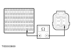
REPEAT the self-test, CLEAR the DTCs. | | A3: CHECK THE DLC CIRCUIT | | | 1 Ignition switch in position 0. | | | 2 Deactivate the SRS. | | | 3 Disconnect Air Bag Control Module C1233. | | | 4 Measure the resistance between the DLC C172 pin 7, circuit 4-JA7 (GY/RD) and the air bag control module C1233 pin 7, circuit 4-JA7 (GY/RD), harness side. | | | Is the resistance less than 5 ohms? Yes INSTALL a new air bag control module.
REFER to: Air Bag Control Module - Vehicles Built From: 02/2000 (501-20B Supplemental Restraint System, Removal and Installation).
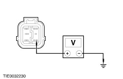
REPEAT the self-test, CLEAR the DTCs. REACTIVATE the system. No REPAIR circuit 4-JA7 (GY/RD). REPEAT the self-test, CLEAR the DTCs. REACTIVATE the system. | | PINPOINT TEST B : DTC B1318: BATTERY VOLTAGE LOW | WARNING:To avoid accidental deployment, the air bag control module backup power supply must be depleted. Wait at least one minute after disconnecting the battery ground cable(s) before commencing any repair or adjustment to the SRS, or any component(s) adjacent to the SRS sensors. Failure to follow these instructions may result in personal injury. | | TEST CONDITIONS | DETAILS/RESULTS/ACTIONS | | B1: CHECK THE BATTERY VOLTAGE | | | 1 Ignition switch in position II. | | | 2 Check the battery voltage. | | | Is the battery voltage greater than 9 volts? Yes No CHECK the battery and charging system.
REFER to: Charging System (414-00 Charging System - General Information, Diagnosis and Testing).
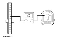
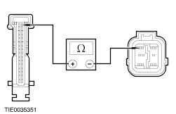
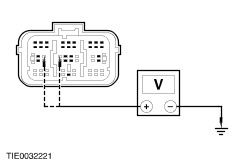
REPEAT the self-test, CLEAR the DTCs. | | B2: CHECK THE AIR BAG CONTROL MODULE SUPPLY CIRCUIT | | | 1 Ignition switch in position 0. | | | 2 Deactivate the SRS. | | | 3 Disconnect Air Bag Control Module C1233. | | | 4 Ignition switch in position II. | | | 5 Measure the voltage between the air bag control module C1233 pin 8, circuit 94-MA10 (VT/OG), harness side and ground. | | | Is the voltage greater than 10 volts? Yes No REPAIR circuit 94-MA10 (VT/OG). REPEAT the self-test, CLEAR the DTCs. REACTIVATE the system. | | B3: CHECK THE AIR BAG CONTROL MODULE SUPPLY CIRCUIT | | | 1 Ignition switch in position 0. | | | 2 Disconnect Fuse 18. | | | 3 Measure the resistance between the air bag control module C1233 pin 8, circuit 91-MA10 (VT/OG), harness side and fuse 18, harness side. | | | Is the resistance less than 5 ohms? Yes REPEAT the self-test, CLEAR the DTCs. REACTIVATE the system. No REPAIR circuit 94-MA10 (VT/OG). REPEAT the self-test, CLEAR the DTCs. REACTIVATE the system. | | PINPOINT TEST C : DTC B1869: AIR BAG WARNING INDICATOR OPEN CIRCUIT OR SHORT TO GROUND | WARNING:To avoid accidental deployment, the air bag control module backup power supply must be depleted. Wait at least one minute after disconnecting the battery ground cable(s) before commencing any repair or adjustment to the SRS, or any component(s) adjacent to the SRS sensors. Failure to follow these instructions may result in personal injury. | | TEST CONDITIONS | DETAILS/RESULTS/ACTIONS | | C1: CHECK THE AIR BAG WARNING INDICATOR | | | 1 Ignition switch in position II. | | | 2 Check the air bag warning indicator. | | | Is the air bag warning indicator illuminated continuously? Yes Vehicles with 1.3L Endura-E (HCS) engine GO to C2. Vehicles with 1.3/1.6L Duratec-8V (Rocam) engine GO to C3. No | | C2: CHECK THE AIR BAG WARNING INDICATOR CIRCUIT - VEHICLES WITH 1.3L ENDURA-E (HCS) ENGINE | | | 1 Ignition switch in position 0. | | | 2 Deactivate the SRS. | | | 3 Disconnect Air Bag Control Module C1233. | | | 4 Disconnect Instrument Cluster C44. | | | 5 Measure the resistance between the instrument cluster C44 pin 8, circuit 91S-MA14 (BK/GN), harness side and the air bag control module C1233 pin 4, circuit 91S-MA14 (BK/GN), harness side. | | | Is the resistance less than 5 ohms? Yes No REPAIR circuit 91S-MA14 (BK/GN). REPEAT the self-test, CLEAR the DTCs. REACTIVATE the system. | | C3: CHECK THE AIR BAG WARNING INDICATOR CIRCUIT - 1.3/1.6L DURATEC-8V (ROCAM) ENGINE | | | 1 Ignition switch in position 0. | | | 2 Deactivate the SRS. | | | 3 Disconnect Air Bag Control Module C1233. | | | 4 Disconnect Instrument Cluster C844. | | | 5 Measure the resistance between the instrument cluster C844 pin 17, circuit 91S-MA14 (BK/GN), harness side and the air bag control module C1233 pin 4, circuit 91S-MA14 (BK/GN), harness side. | | | Is the resistance less than 5 ohms? Yes No REPAIR circuit 91S-MA14 (BK/GN). REPEAT the self-test, CLEAR the DTCs. REACTIVATE the system. | | C4: CHECK THE AIR BAG WARNING INDICATOR FUNCTION | | | 1 Connect Instrument Cluster C44 or C844. | | | 2 Install a fused (7.5A) jumper wire between the air bag control module C1233 pin 4, circuit 91S-MA14 (BK/GN), harness side and ground. | | | 3 Ignition switch in position II. | | | Is the air bag warning indicator illuminated? Yes INSTALL a new instrument cluster.
REFER to: Instrument Cluster (413-01 Instrument Cluster, Removal and Installation).
REPEAT the self-test, CLEAR the DTCs. REACTIVATE the system. No | | C5: CHECK THE INSTRUMENT CLUSTER WARNING INDICATORS | NOTE:The air bag control module will only activate the audible warning if there is an air bag warning indicator fault AND another fault in the SRS (for example an open circuit on the driver air bag module) in all cases REPAIR the air bag warning indicator first. | | | 1 Ignition switch in position 0. | | | 2 Deactivate the SRS. | | | 3 Ignition switch in position II. | | | 4 Check the instrument cluster warning indicators. | | | Are the warning indicators illuminated when the ignition is switched to the ON position? Yes No CHECK the instrument cluster.
REFER to: Instrument Cluster (413-01 Instrument Cluster, Removal and Installation).
REPEAT the self-test, CLEAR the DTCs. REACTIVATE the system. | | C6: CHECK THE AIR BAG WARNING INDICATOR CIRCUIT | | | 1 Ignition switch in position 0. | | | 2 Disconnect Air Bag Control Module C1233. | | | 3 Measure the resistance between the air bag control module C1233 pin 4, circuit 91S-MA14 (BK/GN), harness side and ground. | | | Is the resistance greater than 10,000 ohms? Yes CHECK the air bag warning indicator LED. REPEAT the self-test, CLEAR the DTCs. REACTIVATE the system. No REPAIR circuit 91S-MA14 (BK/GN). REPEAT the self-test, CLEAR the DTCs. REACTIVATE the system. | | C7: CHECK THE AIR BAG WARNING INDICATOR FUNCTION | | | 1 With the fused (7.5A) jumper wire between the air bag control module C1233 pin 4, circuit 91S-MA14 (BK/GN) harness side and ground. | | | 2 Disconnect the fused jumper wire from the ground. | | | Is the air bag warning indicator illuminated? Yes INSTALL a new air bag control module.
REFER to: Air Bag Control Module - Vehicles Built From: 02/2000 (501-20B Supplemental Restraint System, Removal and Installation).
REPEAT the self-test, CLEAR the DTCs. REACTIVATE the system. No CHECK the air bag control module ground G4 for security and corrosion. REPEAT the self-test, CLEAR the DTCs. REACTIVATE the system. | | PINPOINT TEST D : DTC B1870: AIR BAG WARNING INDICATOR SHORT TO BATTERY | WARNING:To avoid accidental deployment, the air bag control module backup power supply must be depleted. Wait at least one minute after disconnecting the battery ground cable(s) before commencing any repair or adjustment to the SRS, or any component(s) adjacent to the SRS sensors. Failure to follow these instructions may result in personal injury. | | TEST CONDITIONS | DETAILS/RESULTS/ACTIONS | | D1: CHECK THE AIR BAG WARNING INDICATOR CIRCUIT | | | 1 Deactivate the SRS. | | | 2 Disconnect Air Bag Control Module C1233. | | | 3 Disconnect Instrument Cluster C44 or C844. | | | 4 Ignition switch in position II. | | | 5 Measure the voltage between the air bag control module C1233 pin 4, circuit 91S-MA14 (BK/GN), harness side and ground. | | | Is any voltage present? Yes REPAIR circuit 91S-MA14 (BK/GN). REPEAT the self-test, CLEAR the DTCs. REACTIVATE the system. No CHECK the instrument cluster.
REFER to: Instrument Cluster (413-01 Instrument Cluster, Removal and Installation).
REPEAT the self-test, CLEAR the DTCs. REACTIVATE the system. | | PINPOINT TEST E : DTC B1871: PASSENGER AIR BAG DEACTIVATION (PAD) SWITCH FAULT – VEHICLES BUILT FROM 02/2005 | WARNING:To avoid accidental deployment, the air bag control module backup power supply must be depleted. Wait at least one minute after disconnecting the battery ground cable(s) before commencing any repair or adjustment to the SRS, or any component(s) adjacent to the SRS sensors. Failure to follow these instructions may result in personal injury. | | TEST CONDITIONS | DETAILS/RESULTS/ACTIONS | | E1: CHECK THE PAD SWITCH CIRCUIT CONTINUITY | | | 1 Deactivate the SRS. | | | 2 Disconnect Air Bag Control Module C1233. | | | 3 Operate the PAD control switch to the ON position. | | | 4 Measure the resistance between the air bag control module C1233 pin 9, circuit 91-JA26 (BK/RD), harness side and the air bag control module C1233 pin 11, circuit 91S-JA26A (BK/RD), harness side. | | | Is the resistance less than 5 ohms? Yes VERIFY the customer concern. REPEAT the self-test, CLEAR the DTCs. REACTIVATE the system. No | | E2: CHECK THE PAD SWITCH TO AIR BAG CONTROL MODULE CIRCUIT CONTINUITY | | | 1 Disconnect PAD Switch C713. | | | 2 Measure the resistance between the: - PAD switch C713 pin 5, circuit 91-JA26 (BK/RD), harness side and the air bag control module C1233 pin 9, circuit 91-JA26 (BK/RD), harness side.
- PAD switch C713 pin 6, circuit 91S-JA26A (BK/RD), harness side and the air bag control module C1233 pin 11, circuit 91S-JA26A (BK/RD), harness side.
| | | Are the resistances less than 5 ohms? Yes INSTALL a new PAD switch. REPEAT the self-test, CLEAR the DTCs. REACTIVATE the system. No REPAIR circuit 91-JA26 (BK/RD) or circuit 91S-JA26A (BK/RD). REPEAT the self-test, CLEAR the DTCs. REACTIVATE the system. | | PINPOINT TEST F : DTC B1877: DRIVER SIDE SHORTING LOOP OPEN CIRCUIT | WARNING:To avoid accidental deployment, the air bag control module backup power supply must be depleted. Wait at least one minute after disconnecting the battery ground cable(s) before commencing any repair or adjustment to the SRS, or any component(s) adjacent to the SRS sensors. Failure to follow these instructions may result in personal injury. | | TEST CONDITIONS | DETAILS/RESULTS/ACTIONS | | F1: CHECK THE AIR BAG CONTROL MODULE CONFIGURATION | | | 1 Check the air bag control module configuration. | | | Does the vehicle have side air bags? Yes REPEAT the self-test, CLEAR the DTCs. If the DTC remains, INSTALL a new air bag control module.
REFER to: Air Bag Control Module - Vehicles Built From: 02/2000 (501-20B Supplemental Restraint System, Removal and Installation).
REPEAT the self-test, CLEAR the DTCs. REACTIVATE the system. No | | F2: CHECK THE WIRING HARNESS FOR OPEN CIRCUIT OR HIGH RESISTANCE | | | 1 Deactivate the SRS. | | | 2 Disconnect Air Bag Control Module C1234. | | | 3 Measure the resistance between the air bag control module C1234 pin 11, circuit 31-JA46 (BK), harness side and the air bag control module C1234 pin 12, circuit 31-JA46 (BK), harness side. | | | Is the resistance less than 5 ohms? Yes REPEAT the self-test, CLEAR the DTCs. If the DTC remains, INSTALL a new air bag control module.
REFER to: Air Bag Control Module - Vehicles Built From: 02/2000 (501-20B Supplemental Restraint System, Removal and Installation).
REPEAT the self-test, CLEAR the DTCs. REACTIVATE the system. No INSTALL a new air bag wiring harness. REPEAT the self-test, CLEAR the DTCs. REACTIVATE the system. | | PINPOINT TEST G : DTC B1878 DRIVER SIDE SHORTING LOOP SHORT TO BATTERY | WARNING:To avoid accidental deployment, the air bag control module backup power supply must be depleted. Wait at least one minute after disconnecting the battery ground cable(s) before commencing any repair or adjustment to the SRS, or any component(s) adjacent to the SRS sensors. Failure to follow these instructions may result in personal injury. | | TEST CONDITIONS | DETAILS/RESULTS/ACTIONS | | G1: CHECK THE AIR BAG CONTROL MODULE CONFIGURATION | | | 1 Check the air bag control module configuration. | | | Does the vehicle have side air bags? Yes REPEAT the self-test, CLEAR the DTCs. If the DTC remains, INSTALL a new air bag control module.
REFER to: Air Bag Control Module - Vehicles Built From: 02/2000 (501-20B Supplemental Restraint System, Removal and Installation).
REPEAT the self-test, CLEAR the DTCs. REACTIVATE the system. No | | G2: CHECK THE DRIVER SIDE SHORTING LOOP CIRCUIT | | | 1 Deactivate the SRS. | | | 2 Disconnect Air Bag Control Module C1234. | | | 3 Ignition switch in position II. | | | 4 Measure the voltage between the: - Air bag control module C1234 pin 11, circuit 31-JA46 (BK), harness side and ground.
- Air bag control module C1234 pin 12, circuit 31-JA46 (BK), harness side and ground.
| | | Is any voltage present? Yes INSTALL a new air bag wiring harness. REPEAT the self-test, CLEAR the DTCs. REACTIVATE the system. No REPEAT the self-test, CLEAR the DTCs. If the DTC remains, INSTALL a new air bag control module.
REFER to: Air Bag Control Module - Vehicles Built From: 02/2000 (501-20B Supplemental Restraint System, Removal and Installation).
REPEAT the self-test, CLEAR the DTCs. REACTIVATE the system. | | PINPOINT TEST H : DTC B1879: DRIVER SIDE SHORTING LOOP SHORT TO GROUND | WARNING:To avoid accidental deployment, the air bag control module backup power supply must be depleted. Wait at least one minute after disconnecting the battery ground cable(s) before commencing any repair or adjustment to the SRS, or any component(s) adjacent to the SRS sensors. Failure to follow these instructions may result in personal injury. | | TEST CONDITIONS | DETAILS/RESULTS/ACTIONS | | H1: CHECK THE AIR BAG CONTROL MODULE CONFIGURATION | | | 1 Check the air bag control module configuration. | | | Does the vehicle have side air bags? Yes REPEAT the self-test, CLEAR the DTCs. If the DTC remains, INSTALL a new air bag control module.
REFER to: Air Bag Control Module - Vehicles Built From: 02/2000 (501-20B Supplemental Restraint System, Removal and Installation).
REPEAT the self-test, CLEAR the DTCs. REACTIVATE the system. No | | H2: CHECK THE DRIVER SIDE SHORTING LOOP CIRCUIT | | | 1 Deactivate the SRS. | | | 2 Disconnect Air Bag Control Module C1234. | | | 3 Measure the resistance between the: - Air bag control module C1234 pin 11, circuit 31-JA46 (BK), harness side and ground.
- Air bag control module C1234 pin 12, circuit 31-JA46 (BK), harness side and ground.
| | | Are the resistances greater than 10,000 ohms? Yes REPEAT the self-test, CLEAR the DTCs. If the DTC remains, INSTALL a new air bag control module.
REFER to: Air Bag Control Module - Vehicles Built From: 02/2000 (501-20B Supplemental Restraint System, Removal and Installation).
REPEAT the self-test, CLEAR the DTCs. REACTIVATE the system. No INSTALL a new air bag wiring harness. REPEAT the self-test, CLEAR the DTCs. REACTIVATE the system. | | PINPOINT TEST I : DTC B1881: PASSENGER SIDE SHORTING LOOP OPEN CIRCUIT | WARNING:To avoid accidental deployment, the air bag control module backup power supply must be depleted. Wait at least one minute after disconnecting the battery ground cable(s) before commencing any repair or adjustment to the SRS, or any component(s) adjacent to the SRS sensors. Failure to follow these instructions may result in personal injury. | | TEST CONDITIONS | DETAILS/RESULTS/ACTIONS | | I1: CHECK THE AIR BAG CONTROL MODULE CONFIGURATION | | | 1 Check the air bag control module configuration. | | | Does the vehicle have side air bags? Yes REPEAT the self-test, CLEAR the DTCs. If the DTC remains, INSTALL a new air bag control module.
REFER to: Air Bag Control Module - Vehicles Built From: 02/2000 (501-20B Supplemental Restraint System, Removal and Installation).
REPEAT the self-test, CLEAR the DTCs. REACTIVATE the system. No | | I2: CHECK THE PASSENGER SIDE SHORTING LOOP CIRCUIT | | | 1 Deactivate the SRS. | | | 2 Disconnect Air Bag Control Module C1234. | | | 3 Measure the resistance between the air bag control module C1234 pin 20, circuit 31-JA46A (BK), harness side and the air bag control module C1234 pin 21, circuit 31-JA46A (BK), harness side. | | | Is the resistance less than 5 ohms? Yes REPEAT the self-test, CLEAR the DTCs. If the DTC remains, INSTALL a new air bag control module.
REFER to: Air Bag Control Module - Vehicles Built From: 02/2000 (501-20B Supplemental Restraint System, Removal and Installation).
REPEAT the self-test, CLEAR the DTCs. REACTIVATE the system. No INSTALL a new air bag wiring harness. REPEAT the self-test, CLEAR the DTCs. REACTIVATE the system. | | PINPOINT TEST J : DTC B1882: PASSENGER SIDE SHORTING LOOP SHORT TO BATTERY | WARNING:To avoid accidental deployment, the air bag control module backup power supply must be depleted. Wait at least one minute after disconnecting the battery ground cable(s) before commencing any repair or adjustment to the SRS, or any component(s) adjacent to the SRS sensors. Failure to follow these instructions may result in personal injury. | | TEST CONDITIONS | DETAILS/RESULTS/ACTIONS | | J1: CHECK THE AIR BAG CONTROL MODULE CONFIGURATION | | | 1 Check the air bag control module configuration. | | | Does the vehicle have side air bags? Yes REPEAT the self-test, CLEAR the DTCs. If the DTC remains, INSTALL a new air bag control module.
REFER to: Air Bag Control Module - Vehicles Built From: 02/2000 (501-20B Supplemental Restraint System, Removal and Installation).
REPEAT the self-test, CLEAR the DTCs. REACTIVATE the system. No | | J2: CHECK THE PASSENGER SIDE SHORTING LOOP CIRCUIT | | | 1 Deactivate the SRS. | | | 2 Disconnect Air Bag Control Module C1234. | | | 3 Ignition switch in position II. | | | 4 Measure the voltage between the: - Air bag control module C1234 pin 20, circuit 31-JA46A (BK), harness side and ground.
- Air bag control module C1234 pin 21, circuit 31-JA46A (BK), harness side and ground.
| | | Is any voltage present? Yes INSTALL a new air bag wiring harness. REPEAT the self-test, CLEAR the DTCs. REACTIVATE the system. No REPEAT the self-test, CLEAR the DTCs. If the DTC remains, INSTALL a new air bag control module.
REFER to: Air Bag Control Module - Vehicles Built From: 02/2000 (501-20B Supplemental Restraint System, Removal and Installation).
REPEAT the self-test, CLEAR the DTCs. REACTIVATE the system. | | PINPOINT TEST K : DTC B1883: PASSENGER SIDE SHORTING LOOP SHORT TO GROUND | WARNING:To avoid accidental deployment, the air bag control module backup power supply must be depleted. Wait at least one minute after disconnecting the battery ground cable(s) before commencing any repair or adjustment to the SRS, or any component(s) adjacent to the SRS sensors. Failure to follow these instructions may result in personal injury. | | TEST CONDITIONS | DETAILS/RESULTS/ACTIONS | | K1: CHECK THE AIR BAG CONTROL MODULE CONFIGURATION | | | 1 Check the air bag control module configuration. | | | Does the vehicle have side air bags? Yes REPEAT the self-test, CLEAR the DTCs. If the DTC remains, INSTALL a new air bag control module.
REFER to: Air Bag Control Module - Vehicles Built From: 02/2000 (501-20B Supplemental Restraint System, Removal and Installation).
REPEAT the self-test, CLEAR the DTCs. REACTIVATE the system. No | | K2: CHECK THE PASSENGER SIDE SHORTING LOOP CIRCUIT | | | 1 Deactivate the SRS. | | | 2 Disconnect Air Bag Control Module C1234. | | | 3 Measure the resistance between the: - Air bag control module C1234 pin 20, circuit 31-JA46A (BK), harness side and ground.
- Air bag control module C1234 pin 21, circuit 31-JA46A (BK), harness side and ground.
| | | Are the resistances greater than 10,000 ohms? Yes REPEAT the self-test, CLEAR the DTCs. If the DTC remains, INSTALL a new air bag control module.
REFER to: Air Bag Control Module - Vehicles Built From: 02/2000 (501-20B Supplemental Restraint System, Removal and Installation).
REPEAT the self-test, CLEAR the DTCs. REACTIVATE the system. No INSTALL a new air bag wiring harness. REPEAT the self-test, CLEAR the DTCs. REACTIVATE the system. | | PINPOINT TEST L : DTC B1884: PASSENGER AIR BAG DEACTIVATION (PAD) WARNING INDICATOR INOPERATIVE – VEHICLES BUILT FROM 02/2005 | WARNING:To avoid accidental deployment, the air bag control module backup power supply must be depleted. Wait at least one minute after disconnecting the battery ground cable(s) before commencing any repair or adjustment to the SRS, or any component(s) adjacent to the SRS sensors. Failure to follow these instructions may result in personal injury. | | TEST CONDITIONS | DETAILS/RESULTS/ACTIONS | | L1: CHECK THE PAD WARNING INDICATOR CIRCUIT FOR CONTINUITY | | | 1 Deactivate the SRS. | | | 2 Disconnect Air Bag Control Module C1233. | | | 3 Measure the resistance between the air bag control module C1233 pin 10, circuit 94S-JA26 (VT/OG), harness side and the air bag control module C1233 pin 9, circuit 91-JA26 (BK/RD), harness side. | | | Is the resistance less than 5 ohms? Yes No | | L2: CHECK THE PAD WARNING INDICATOR CIRCUIT FOR A SHORT TO GROUND | | | 1 Measure the resistance between the air bag control module C1233 pin 10, circuit 94S-JA26 (VT/OG), harness side and ground. | | | Is the resistance greater than 10,000 ohms? Yes REPEAT the self-test, CLEAR the DTCs. REACTIVATE the system. No | | L3: CHECK FOR CONTINUITY BETWEEN THE PAD SWITCH AND THE AIR BAG CONTROL MODULE CIRCUIT | | | 1 Disconnect PAD Switch C713. | | | 2 Measure the resistance between the PAD switch C713 pin 5, circuit 91S-JA26 (BK/RD), harness side and the air bag control module C1233 pin 9, circuit 91-JA26 (BK/RD), harness side. | | | Is the resistance less than 5 ohms? Yes No REPAIR circuit 91-JA26 (BK/RD). REPEAT the self-test, CLEAR the DTCs. REACTIVATE the system. | | L4: CHECK FOR CONTINUITY BETWEEN THE AIR BAG CONTROL MODULE AND THE PAD SWITCH CIRCUIT | | | 1 Measure the resistance between the PAD switch C713 pin 4, circuit 91S-JA26 (BK/RD), harness side and the air bag control module C1233 pin 10, circuit 94S-JA26 (VT/OG), harness side. | | | Is the resistance less than 5 ohms? Yes INSTALL a new PAD switch.
REFER to: Passenger Air Bag Deactivation (PAD) Switch - Vehicles Built From: 02/2005 (501-20B Supplemental Restraint System, Removal and Installation).
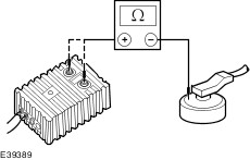
REPEAT the self-test, CLEAR the DTCs. REACTIVATE the system. No | | L5: CHECK THE PAD SWITCH CIRCUIT FOR A SHORT TO GROUND | | | 1 Disconnect PAD Switch C713. | | | 2 Measure the resistance between the air bag control module C1233 pin 9, circuit 91-JA26 (BK/RD), harness side and ground. | | | Is the resistance greater than 10,000 ohms? Yes No REPAIR circuit 91-JA26 (BK/RD). REPEAT the self-test, CLEAR the DTCs. REACTIVATE the system. | | L6: CHECK THE PAD WARNING INDICATOR CIRCUIT FOR A SHORT TO GROUND | | | 1 Disconnect PAD Indicator C181. | | | 2 Measure the resistance between the air bag control module C1233 pin 10, circuit 94S-JA26 (VT/OG), harness side and ground. | | | Is the resistance greater than 10,000 ohms? Yes REPAIR circuit 91S-JA26 (BK/RD). REPEAT the self-test, CLEAR the DTCs. REACTIVATE the system. No REPAIR circuit 94S-JA26 (VT/OG). REPEAT the self-test, CLEAR the DTCs. REACTIVATE the system. | | L7: CHECK FOR CONTINUITY BETWEEN THE AIR BAG CONTROL MODULE AND THE PAD WARNING INDICATOR | | | 1 Disconnect PAD Warning Indicator C181. | | | 2 Measure the resistance between the air bag control module C1233 pin 10, circuit 94S-JA26 (VT/OG), harness side and the PAD warning indicator C181 pin 5, circuit 94S-JA26 (VT/OG), harness side. | | | Is the resistance less than 5 ohms? Yes No REPAIR circuit 94S-JA26 (VT/OG). REPEAT the self-test, CLEAR the DTCs. REACTIVATE the system. | | L8: CHECK FOR CONTINUITY BETWEEN THE PAD SWITCH AND THE PAD WARNING INDICATOR | | | 1 Measure the resistance between the PAD switch C713 pin 4, circuit 91S-JA26 (BK/RD), harness side and the PAD warning indicator C181 pin 2, circuit 91S-JA26 (BK/RD), harness side. | | | Is the resistance less than 5 ohms? Yes INSTALL a new PAD warning indicator. REPEAT the self-test, CLEAR the DTCs. REACTIVATE the system. No REPAIR circuit 91S-JA26 (BK/RD). REPEAT the self-test, CLEAR the DTCs. REACTIVATE the system. | | PINPOINT TEST M : DTC B1887: DRIVER AIR BAG SHORT TO GROUND | WARNING:To avoid accidental deployment, the air bag control module backup power supply must be depleted. Wait at least one minute after disconnecting the battery ground cable(s) before commencing any repair or adjustment to the SRS, or any component(s) adjacent to the SRS sensors. Failure to follow these instructions may result in personal injury. | | TEST CONDITIONS | DETAILS/RESULTS/ACTIONS | | M1: CHECK THE DRIVER AIR BAG CIRCUIT | | | 1 Deactivate the SRS. | | | 2 Ignition switch in position II. | | | 3 Carry out the self-test with the simulators installed. | | | Does the system prove out correctly? Yes No | | M2: CHECK THE DRIVER AIR BAG MODULE | WARNING:Do not proceed with this test unless using WDS. Failure to follow this instruction may result in personal injury. | | | 1 Ignition switch in position 0. | | | 2 Connect Test and Deployment Lead to the driver air bag module. | | | 3 Select DMM specific on WDS. | | | 4 Connect the Test and Deployment lead to WDS. | | | 5 Measure the resistance between each of the terminals and the driver air bag module casing. | | | Are the resistances greater than 10,000 ohms? Yes REPEAT the self-test, CLEAR the DTCs. REACTIVATE the system. No INSTALL a new driver air bag module.
REFER to: Driver Air Bag Module (501-20B Supplemental Restraint System, Removal and Installation).
REPEAT the self-test, CLEAR the DTCs. REACTIVATE the system. | | M3: CHECK THE AIR BAG WIRING HARNESS FOR A SHORT TO GROUND | | | 1 Ignition switch in position 0. | | | 2 Disconnect Air Bag Control Module C1233. | | | 3 Disconnect Driver Air Bag Module Simulator. | | | 4 Measure the resistance between the: - Air bag control module C1233 pin 2, circuit 94S-MA8 (VT), harness side and ground.
- Air bag control module C1233 pin 3, circuit 91S-MA8 (BK/OG), harness side and ground.
| | | 5 Turn the steering wheel from lock to lock and note the resistance readings. | | | Are the resistances greater than 10,000 ohms? Yes REPEAT the self-test, CLEAR the DTCs. REACTIVATE the system. No | | M4: CHECK THE CLOCKSPRING FOR A SHORT TO GROUND | | | 1 Disconnect Clockspring C150. | | | 2 Measure the resistance between the: - Air bag control module C1233 pin 2, circuit 94S-MA8 (VT), harness side and ground.
- Air bag control module C1233 pin 3, circuit 91S-MA8 (BK/OG), harness side and ground.
| | | Are the resistances greater than 10,000 ohms? Yes INSTALL a new clockspring.
REFER to: Clockspring - Vehicles Built From: 02/2000 (501-20B Supplemental Restraint System, Removal and Installation).
REPEAT the self-test , CLEAR the DTCs. REACTIVATE the system. No REPAIR circuit 94S-MA8 (VT) or circuit 91S-MA8 (BK/OG). REPEAT the self-test CLEAR the DTCs. REACTIVATE the system. | | PINPOINT TEST N : DTC B1888: PASSENGER AIR BAG SHORT TO GROUND | WARNING:To avoid accidental deployment, the air bag control module backup power supply must be depleted. Wait at least one minute after disconnecting the battery ground cable(s) before commencing any repair or adjustment to the SRS, or any component(s) adjacent to the SRS sensors. Failure to follow these instructions may result in personal injury. | | TEST CONDITIONS | DETAILS/RESULTS/ACTIONS | | N1: CHECK THE PASSENGER AIR BAG CIRCUIT | | | 1 Deactivate the SRS. | | | 2 Ignition switch in position II. | | | 3 Carry out the self-test with the simulators installed. | | | Does the system prove out correctly? Yes No | | N2: CHECK THE PASSENGER AIR BAG MODULE | WARNING:Do not proceed with this test unless using WDS. Failure to follow this instruction may result in personal injury. | | | 1 Connect the Test and Deployment Lead to the passenger air bag module. | | | 2 Select DMM Specific on WDS. | | | 3 Connect the Test and Deployment Lead to WDS. | | | 4 Measure the resistance between each of the terminals and the passenger air bag module casing. | | | Are the resistances greater than 10,000 ohms? Yes REPEAT the self-test, CLEAR the DTCs. REACTIVATE the system. No INSTALL a new passenger air bag module.
REFER to: Passenger Air Bag Module (501-20B Supplemental Restraint System, Removal and Installation).
REPEAT the self-test, CLEAR the DTCs. REACTIVATE the system. | | N3: CHECK THE PASSENGER AIR BAG CIRCUIT FOR A SHORT TO GROUND | | | 1 Ignition switch in position 0. | | | 2 Disconnect Air Bag Control Module C1233. | | | 3 Disconnect Passenger Air Bag Module Simulator. | | | 4 Measure the resistance between the: - Air bag control module C1233 pin 5, circuit 94S-MA31 (VT/WH), harness side and ground.
- Air bag control module C1233 pin 6, circuit 91S-MA31 (BK/WH), harness side and ground.
| | | Are the resistances greater than 10,000 ohms? Yes REPEAT the self-test, CLEAR the DTCs. REACTIVATE the system. No REPAIR circuit 91S-MA31 (BK/WH) or circuit 94S-MA31 (VT/WH). REACTIVATE the system. | | PINPOINT TEST O : DTC B1890: PASSENGER AIR BAG DEACTIVATION (PAD) WARNING INDICATOR CIRCUIT SHORT TO BATTERY – VEHICLES BUILT FROM 02/2005 | WARNING:To avoid accidental deployment, the air bag control module backup power supply must be depleted. Wait at least one minute after disconnecting the battery ground cable(s) before commencing any repair or adjustment to the SRS, or any component(s) adjacent to the SRS sensors. Failure to follow these instructions may result in personal injury. | | TEST CONDITIONS | DETAILS/RESULTS/ACTIONS | | O1: CHECK THE PAD WARNING INDICATOR HARNESS FOR A SHORT TO POWER | | | 1 Deactivate the SRS. | | | 2 Disconnect Air Bag Control Module C1233. | | | 3 Ignition switch in position II. | | | 4 Measure the voltage between the: - Air bag control module C1233 pin 9, circuit 91-JA26 (BK/RD), harness side and ground.
- Air bag control module C1233 pin 10, circuit 94S-JA26 (VT/OG), harness side and ground.
| | | Is any voltage present? Yes No INSTALL a new air bag control module.
REFER to: Air Bag Control Module - Vehicles Built From: 02/2000 (501-20B Supplemental Restraint System, Removal and Installation).
REPEAT the self-test, CLEAR the DTCs. REACTIVATE the system. | | O2: CHECK THE PAD WARNING INDICATOR FOR A SHORT TO POWER | | | 1 Disconnect PAD Warning Indicator C181. | | | 2 Measure the voltage between the: - Air bag control module C1233 pin 9, circuit 91-JA26 (BK/RD), harness side and ground.
- Air bag control module C1233 pin 10, circuit 94S-JA26 (VT/OG), harness side and ground.
| | | Is any voltage present? Yes REPAIR circuit 91-JA26 (BK/RD) or circuit 94S-JA26 (VT/OG). REPEAT the self-test, CLEAR the DTCs. REACTIVATE the system. No INSTALL a new PAD warning indicator. REPEAT the self-test, CLEAR the DTCs. REACTIVATE the system. | | PINPOINT TEST P : DTC B1916: DRIVER AIR BAG SHORT TO BATTERY | WARNING:To avoid accidental deployment, the air bag control module backup power supply must be depleted. Wait at least one minute after disconnecting the battery ground cable(s) before commencing any repair or adjustment to the SRS, or any component(s) adjacent to the SRS sensors. Failure to follow these instructions may result in personal injury. | | TEST CONDITIONS | DETAILS/RESULTS/ACTIONS | | P1: CHECK THE AIR BAG WIRING HARNESS FOR A SHORT TO BATTERY | | | 1 Deactivate the SRS. | | | 2 Disconnect Driver Air Bag Module Simulator. | | | 3 Disconnect Air Bag Control Module C1233. | | | 4 Ignition switch in position II. | | | 5 Measure the voltage between the: - Air bag control module C1233 pin 2, circuit 94S-MA8 (VT), harness side and ground.
- Air bag control module C1233 pin 3, circuit 91S-MA8 (BK/OG), harness side and ground.
| | | Is any voltage present? Yes No CONNECT the driver air bag module simulator and air bag control module. REPEAT the self-test, CLEAR the DTCs. REACTIVATE the system. | | P2: CHECK THE CLOCKSPRING FOR A SHORT TO BATTERY OR IGNITION | | | 1 Ignition switch in position 0. | | | 2 Disconnect Clockspring C150. | | | 3 Ignition switch in position II. | | | 4 Measure the voltage between the: - Air bag control module C1233 pin 2, circuit 94S-MA8 (VT), harness side and ground.
- Air bag control module C1233 pin 3, circuit 91S-MA8 (BK/OG), harness side and ground.
| | | Is any voltage present? Yes REPAIR circuit 91S-MA8 (BK/OG) or circuit 94S-MA8 (VT). REPEAT the self-test, CLEAR the DTCs. REACTIVATE the system. No INSTALL a new Clockspring.
REFER to: Clockspring - Vehicles Built From: 02/2000 (501-20B Supplemental Restraint System, Removal and Installation).
REPEAT the self-test, CLEAR the DTCs. REACTIVATE the system. | | PINPOINT TEST Q : DTC:B1925: PASSENGER AIR BAG SHORT TO BATTERY | WARNING:To avoid accidental deployment, the air bag control module backup power supply must be depleted. Wait at least one minute after disconnecting the battery ground cable(s) before commencing any repair or adjustment to the SRS, or any component(s) adjacent to the SRS sensors. Failure to follow these instructions may result in personal injury. | | TEST CONDITIONS | DETAILS/RESULTS/ACTIONS | | Q1: CHECK THE PASSENGER AIR BAG CIRCUIT FOR A SHORT TO BATTERY | | | 1 Deactivate the SRS. | | | 2 Disconnect Passenger Air Bag Module Simulator. | | | 3 Disconnect Air Bag Control Module C1233. | | | 4 Ignition switch in position II. | | | 5 Measure the voltage between the: - Air bag control module C1233 pin 5, circuit 94S-MA31 (VT/WH), harness side and ground.
- Air bag control module C1233 pin 6, circuit 91S-MA31 (BK/WH), harness side and ground.
| | | Is any voltage present? Yes REPAIR circuit 91S-MA31 (BK/WH) or circuit 94S-MA31 (VT/WH). REPEAT the self-test, CLEAR the DTCs. REACTIVATE the system. No CONNECT the passenger air bag module simulator and air bag control module. REPEAT the self-test, CLEAR the DTCs. REACTIVATE the system. | | PINPOINT TEST R : DTC B1932: DRIVER AIR BAG OPEN CIRCUIT OR HIGH RESISTANCE | WARNING:To avoid accidental deployment, the air bag control module backup power supply must be depleted. Wait at least one minute after disconnecting the battery ground cable(s) before commencing any repair or adjustment to the SRS, or any component(s) adjacent to the SRS sensors. Failure to follow these instructions may result in personal injury. | | TEST CONDITIONS | DETAILS/RESULTS/ACTIONS | | R1: CHECK THE DRIVER AIR BAG MODULE CIRCUIT RESISTANCE | | | 1 Deactivate the SRS. | | | 2 Ignition switch in position II. | | | 3 Carry out the self-test with the air bag simulators installed. | | | Does the system prove out correctly? Yes No | | R2: CHECK THE DRIVER AIR BAG MODULE SQUIB RESISTANCE | WARNING:Do not proceed with this test unless using WDS. Failure to follow this instruction may result in personal injury. | | | 1 Connect the Test and Deployment Lead to the driver air bag module. | | | 2 Select DMM specific on WDS. | | | 3 Connect the Test and Deployment Lead to WDS. | | | 4 Measure the resistance of the driver air bag module squib. | | | Is the resistance between 2 and 3 ohms? Yes REPEAT the self-test, CLEAR the DTCs. REACTIVATE the system. No INSTALL a new driver air bag module.
REFER to: Driver Air Bag Module (501-20B Supplemental Restraint System, Removal and Installation).
REPEAT the self-test, CLEAR the DTCs. REACTIVATE the system. | | R3: CHECK THE CLOCKSPRING FOR OPEN CIRCUIT OR HIGH RESISTANCE | | | 1 Ignition switch in position 0. | | | 2 Disconnect Clockspring C150. | | | 3 Disconnect Air Bag Control Module C1233. | | | 4 Measure the resistance between the: - Air bag control module C1233 pin 2, circuit 94S-MA8 (VT), harness side and the clockspring C150 pin 3, circuit 94S-MA8 (VT), harness side.
- Air bag control module C1233 pin 3, circuit 91S-MA8 (BK/OG), harness side and the clockspring C150 pin 1, circuit 91S-MA8 (BK/OG), harness side.
| | | Are the resistance less than 5 ohms? Yes INSTALL a new clockspring.
REFER to: Clockspring - Vehicles Built From: 02/2000 (501-20B Supplemental Restraint System, Removal and Installation).
REPEAT the self-test, CLEAR the DTCs. REACTIVATE the system. No REPAIR circuit 91S-MA8 (BK/OG) or circuit 94S-MA8 (VT). REPEAT the self-test, CLEAR the DTCs. REACTIVATE the system. | | PINPOINT TEST S : DTC: B1933: PASSENGER AIR BAG OPEN CIRCUIT OR HIGH RESISTANCE | WARNING:To avoid accidental deployment, the air bag control module backup power supply must be depleted. Wait at least one minute after disconnecting the battery ground cable(s) before commencing any repair or adjustment to the SRS, or any component(s) adjacent to the SRS sensors. Failure to follow these instructions may result in personal injury. | | TEST CONDITIONS | DETAILS/RESULTS/ACTIONS | | S1: CHECK THE PASSENGER AIR BAG MODULE CIRCUIT RESISTANCE | | | 1 Deactivate the SRS. | | | 2 Ignition switch in position II. | | | 3 Carry out the self-test with the simulators installed. | | | Does the system prove out correctly? Yes No REPAIR circuit 91S-MA31 (BK/WH) or circuit 94S-MA31 (VT/WH). REFER to the Wiring Diagrams. REPEAT the self-test, CLEAR the DTCs. REACTIVATE the system. | | S2: CHECK THE PASSENGER AIR BAG MODULE SQUIB RESISTANCE | WARNING:Do not proceed with this test unless using WDS. Failure to follow this instruction may result in personal injury. | | | 1 Connect the Test and Deployment Lead to the passenger air bag module. | | | 2 Select DMM specific on WDS. | | | 3 Connect the Test and Deployment lead to WDS. | | | 4 Measure the resistance of the passenger air bag module squib. | | | Is the resistance between 2 and 3 ohms? Yes REPEAT the self-test, CLEAR the DTCs. REACTIVATE the system. No INSTALL a new passenger air bag module.
REFER to: Passenger Air Bag Module (501-20B Supplemental Restraint System, Removal and Installation).
REPEAT the self-test, CLEAR the DTCs. REACTIVATE the system. | | PINPOINT TEST T : DTC B1934: DRIVER AIR BAG CIRCUIT LOW RESISTANCE | WARNING:To avoid accidental deployment, the air bag control module backup power supply must be depleted. Wait at least one minute after disconnecting the battery ground cable(s) before commencing any repair or adjustment to the SRS, or any component(s) adjacent to the SRS sensors. Failure to follow these instructions may result in personal injury. | | TEST CONDITIONS | DETAILS/RESULTS/ACTIONS | | T1: CHECK THE DRIVER AIR BAG MODULE CIRCUIT RESISTANCE | | | 1 Deactivate the SRS. | | | 2 Ignition switch in position II. | | | 3 Carry out the self-test with the simulators installed. | | | Does the system prove out correctly? Yes No | | T2: CHECK THE DRIVER AIR BAG MODULE SQUIB RESISTANCE | WARNING:Do not proceed with this test unless using WDS. Failure to follow this instruction may result in personal injury. | | | 1 Connect the Test and Deployment Lead to the driver air bag module. | | | 2 Select DMM specific on WDS. | | | 3 Connect the Test and Deployment Lead WDS. | | | 4 Measure the resistance of the driver air bag module squib. | | | Is the resistance between 2 and 3 ohms? Yes REPEAT the self-test, CLEAR the DTCs. REACTIVATE the system. No INSTALL a new driver air bag module.
REFER to: Driver Air Bag Module (501-20B Supplemental Restraint System, Removal and Installation).
REPEAT the self-test, CLEAR the DTCs. REACTIVATE the system. | | T3: CHECK THE CLOCKSPRING FOR LOW RESISTANCE | | | 1 Ignition switch in position 0. | | | 2 Disconnect Clockspring C150. | | | 3 Disconnect Air Bag Control Module C1233. | | | 4 Measure the resistance between the air bag control module C1233 pin 2, circuit 94S-MA8 (VT) and the air bag control module C1233 pin 3, circuit 91S-MA8 (BK/OG), harness side. | | | Is the resistance greater than 10,000 ohms? Yes INSTALL a new Clockspring.
REFER to: Clockspring - Vehicles Built From: 02/2000 (501-20B Supplemental Restraint System, Removal and Installation).
REPEAT the self-test, CLEAR the DTCs. REACTIVATE the system. No REPAIR circuit 91S-MA8 (BK/OG) or circuit 94S-MA8 (VT). REPEAT the self-test, CLEAR the DTCs. REACTIVATE the system. | | PINPOINT TEST U : DTC B1935: PASSENGER AIR BAG CIRCUIT LOW RESISTANCE | WARNING:To avoid accidental deployment, the air bag control module backup power supply must be depleted. Wait at least one minute after disconnecting the battery ground cable(s) before commencing any repair or adjustment to the SRS, or any component(s) adjacent to the SRS sensors. Failure to follow these instructions may result in personal injury. | | TEST CONDITIONS | DETAILS/RESULTS/ACTIONS | | U1: CHECK THE PASSENGER AIR BAG MODULE CIRCUIT RESISTANCE | | | 1 Deactivate the SRS. | | | 2 Ignition switch in position II. | | | 3 Carry out the self-test with the simulators installed. | | | Does the system prove out correctly? Yes No | | U2: CHECK THE PASSENGER AIR BAG MODULE SQUIB RESISTANCE | WARNING:Do not proceed with this test unless using WDS. Failure to follow this instruction may result in personal injury. | | | 1 Connect the Test and Deployment Lead to the passenger air bag module. | | | 2 Select DMM specific on WDS. | | | 3 Connect the TEST and Deployment Lead to WDS. | | | 4 Measure the resistance of the passenger air bag module squib. | | | Is the resistance between 2 and 3 ohms? Yes REPEAT the self-test, CLEAR the DTCs. REACTIVATE the system. No INSTALL a new passenger air bag module.
REFER to: Passenger Air Bag Module (501-20B Supplemental Restraint System, Removal and Installation).
REPEAT the self-test, CLEAR the DTCs. REACTIVATE the system. | | U3: CHECK THE PASSENGER AIR BAG CIRCUIT FOR LOW RESISTANCE | | | 1 Ignition switch in position 0. | | | 2 Disconnect Passenger Air Bag Module Simulator. | | | 3 Disconnect Air Bag Control Module C1233. | | | 4 Measure the resistance between the air bag control module C1233 pin 5, circuit 94S-MA31 (VT/WH) and the air bag control module C1233 pin 6, circuit 91S-MA31 (BK/WH), harness side. | | | Is the resistance greater than 10,000 ohms? Yes REPEAT the self-test, CLEAR the DTCs. REACTIVATE the system. No REPAIR circuit 91S-MA31 (BK/WH) and circuit 94S-MA31 (VT/WH). REPEAT the self-test, CLEAR the DTCs. REACTIVATE the system. | | PINPOINT TEST V : DTC B1992: DRIVER SIDE, SIDE AIR BAG SHORT TO BATTERY - VEHICLES BUILT UP TO 09/2000 | WARNING:To avoid accidental deployment, the air bag control module backup power supply must be depleted. Wait at least one minute after disconnecting the battery ground cable(s) before commencing any repair or adjustment to the SRS, or any component(s) adjacent to the SRS sensors. Failure to follow these instructions may result in personal injury. | | TEST CONDITIONS | DETAILS/RESULTS/ACTIONS | | V1: CHECK THE DRIVER SIDE, SIDE AIR BAG CIRCUIT | | | 1 Deactivate the SRS. | | | 2 Ignition switch in position II. | | | 3 Carry out the self-test with the simulators installed. | | | Does the system prove out correctly? Yes REPEAT the self-test, CLEAR the DTCS. REACTIVATE the system. No | | V2: CHECK THE DRIVER SIDE, SIDE AIR BAG CIRCUIT FOR A SHORT TO BATTERY | | | 1 Ignition switch in position 0. | | | 2 Disconnect Air Bag Control Module C1234. | | | 3 Ignition switch in position II. | | | 4 Measure the voltage between the: - Air bag control module C1234 pin 15, circuit 94-JA37 (VT/BK), harness side and ground.
- Air bag control module C1234 pin 16, circuit 91S-JA37 (BK/GN), harness side and ground.
| | | Is any voltage present? Yes REPAIR circuit 91S-JA37 (BK/GN) or circuit 94-JA37 (VT/BK) and circuit 94-MA10 (VT/OG). REPEAT the self-test, CLEAR the DTCs. REACTIVATE the system. No REPEAT the self-test, CLEAR the DTCs. REACTIVATE the system. | | PINPOINT TEST W : DTC B1992: DRIVER SIDE, SIDE AIR BAG SHORT TO BATTERY - VEHICLES BUILT FROM 09/2000 | WARNING:To avoid accidental deployment, the air bag control module backup power supply must be depleted. Wait at least one minute after disconnecting the battery ground cable(s) before commencing any repair or adjustment to the SRS, or any component(s) adjacent to the SRS sensors. Failure to follow these instructions may result in personal injury. | | TEST CONDITIONS | DETAILS/RESULTS/ACTIONS | | W1: CHECK THE DRIVER SIDE, SIDE AIR BAG CIRCUIT | | | 1 Deactivate the SRS. | | | 2 Ignition switch in position II. | | | 3 Carry out the self-test with the simulators installed. | | | Does the system prove out correctly? Yes REPEAT the self-test, CLEAR the DTCS. REACTIVATE the system. No | | W2: CHECK THE DRIVER SIDE, SIDE AIR BAG CIRCUIT FOR A SHORT TO BATTERY | | | 1 Ignition switch in position 0. | | | 2 Disconnect Air Bag Control Module C1234. | | | 3 Ignition switch in position II. | | | 4 Measure the voltage between the: LHD Vehicles - Air bag control module C1234 pin 15, circuit 94-JA42 (VT/BK), harness side and ground.
- Air bag control module C1234 pin 16, circuit 91S-JA42 (BK/GN), harness side and ground.
| | | RHD Vehicles - Air bag control module C1234 pin 23, circuit 94-JA44 (VT/OG), harness side and ground.
- Air bag control module C1234 pin 24, circuit 91S-JA44 (BK/RD), harness side and ground.
| | | Is any voltage present? Yes LHD Vehicles - REPAIR circuits 91S-JA42 (BK/GN) or circuit 94-JA42 (VT/BK) and circuit 94-MA10 (VT/OG). REPEAT the self-test, CLEAR the DTCs. REACTIVATE the system. RHD Vehicles - REPAIR circuits 94-JA44 (VT/OG) or circuit 91S-JA44 (BK/RD) and circuit 94-MA10 (VT/OG) (RHD). REPEAT the self-test, CLEAR the DTCs. REACTIVATE the system. No REPEAT the self-test, CLEAR the DTCs. REACTIVATE the system. | | PINPOINT TEST X : DTC B1993: DRIVER SIDE, SIDE AIR BAG SHORT TO GROUND - VEHICLES BUILT UP TO 09/2000 | WARNING:To avoid accidental deployment, the air bag control module backup power supply must be depleted. Wait at least one minute after disconnecting the battery ground cable(s) before commencing any repair or adjustment to the SRS, or any component(s) adjacent to the SRS sensors. Failure to follow these instructions may result in personal injury. | | TEST CONDITIONS | DETAILS/RESULTS/ACTIONS | | X1: DTC: CHECK THE DRIVER SIDE, SIDE AIR BAG CIRCUIT | | | 1 Deactivate the SRS. | | | 2 Ignition switch in position II. | | | 3 Carry out the self-test with the simulators installed. | | | Does the system prove out correctly? Yes No | | X2: CHECK THE DRIVER SIDE, SIDE AIR BAG MODULE | | | 1 Ignition switch in position 0. | | | 2 Connect the Test and Deployment Lead to the driver side, side air bag module. | | | 3 Select DMM Specific on WDS. | | | 4 Connect the Test and Deployment Lead to WDS. | | | 5 Measure the resistance between each of the terminals and the driver side, side air bag module casing. | | | Is the resistance greater than 10,000 ohms? Yes REPEAT the self-test, CLEAR the DTCs. REACTIVATE the system. No INSTALL a new driver side, side air bag module.
REFER to: Side Air Bag Module (501-20B Supplemental Restraint System, Removal and Installation).
REPEAT the self-test, CLEAR the DTCs. REACTIVATE the system. | | X3: CHECK THE DRIVER SIDE, SIDE AIR BAG CIRCUIT FOR A SHORT TO GROUND | | | 1 Ignition switch in position 0. | | | 2 Disconnect Air Bag Control Module C1234. | | | 3 Disconnect Driver Side, Side Air Bag Simulator. | | | 4 Measure the resistance between the: - air bag control module C1234 pin 15, circuit 94-JA37 (VT/BK), harness side and ground.
- air bag control module C1234 pin 16, circuit 91S-JA37 (BK/GN), harness side and ground.
| | | Are the resistances greater than 10,000 ohms? Yes REPEAT the self-test, CLEAR the DTCs. REACTIVATE the system. No REPAIR circuit 91S-JA37 (BK/GN) or circuit 94-JA37 (VT/BK). REPEAT the self-test, CLEAR the DTCs. REACTIVATE the system. | | PINPOINT TEST Y : DTC B1993: DRIVER SIDE, SIDE AIR BAG SHORT TO GROUND - VEHICLES BUILT FROM 09/2000 | WARNING:To avoid accidental deployment, the air bag control module backup power supply must be depleted. Wait at least one minute after disconnecting the battery ground cable(s) before commencing any repair or adjustment to the SRS, or any component(s) adjacent to the SRS sensors. Failure to follow these instructions may result in personal injury. | | TEST CONDITIONS | DETAILS/RESULTS/ACTIONS | | Y1: DTC: CHECK THE DRIVER SIDE, SIDE AIR BAG CIRCUIT | | | 1 Deactivate the SRS. | | | 2 Ignition switch in position II. | | | 3 Carry out the self-test with the simulators installed. | | | Does the system prove out correctly? Yes No | | Y2: CHECK THE DRIVER SIDE, SIDE AIR BAG MODULE | WARNING:Do not proceed with this test unless using WDS. Failure to follow this instruction may result in personal injury. | | | 1 Ignition switch in position 0. | | | 2 Connect the Test and Deployment Lead to the driver side, side air bag module. | | | 3 Select DMM Specific on WDS. | | | 4 Connect the Test and Deployment Lead to WDS. | | | 5 Measure the resistance between each of the terminals and the driver side, side air bag module casing. | | | Is the resistance greater than 10,000 ohms? Yes REPEAT the self-test, CLEAR the DTCs. REACTIVATE the system. No INSTALL a new driver side, side air bag module.
REFER to: Side Air Bag Module (501-20B Supplemental Restraint System, Removal and Installation).
REPEAT the self-test, CLEAR the DTCs. REACTIVATE the system. | | Y3: CHECK THE DRIVER SIDE, SIDE AIR BAG CIRCUIT FOR A SHORT TO GROUND | | | 1 Ignition switch in position 0. | | | 2 Disconnect Air Bag Control Module C1234. | | | 3 Disconnect Driver Side, Side Air Bag Simulator. | | | 4 Measure the resistance between the: LHD Vehicles - Air bag control module C1234 pin 15, circuit 94-JA42 (VT/BK), harness side and ground.
- Air bag control module C1234 pin 16, circuit 91S-JA42 (BK/GN), harness side and ground.
| | | RHD Vehicles - Air bag control module C1234 pin 23, circuit 94-JA44 (VT/OG), harness side and ground.
- Air bag control module C1234 pin 24, circuit 91S-JA44 (BK/RD), harness side and ground.
| | | Are the resistances greater than 10,000 ohms? Yes REPEAT the self-test, CLEAR the DTCs. REACTIVATE the system. No LHD Vehicles - REPAIR circuit 91S-JA42 (BK/GN) or circuit 94-JA42 (VT/BK) and circuit 94-MA10 (VT/OG). REPEAT the self-test, CLEAR the DTCs. REACTIVATE the system. RHD Vehicles - REPAIR circuit 91S-JA44 (BK/RD) or circuit 94-JA44 (VT/OG) and circuit 94-MA10 (VT/OG). REPEAT the self-test, CLEAR the DTCs. REACTIVATE the system. | | PINPOINT TEST Z : DTC B1994: DRIVER SIDE, SIDE AIR BAG OPEN CIRCUIT - VEHICLES BUILT UP TO 09/2000 | WARNING:To avoid accidental deployment, the air bag control module backup power supply must be depleted. Wait at least one minute after disconnecting the battery ground cable(s) before commencing any repair or adjustment to the SRS, or any component(s) adjacent to the SRS sensors. Failure to follow these instructions may result in personal injury. | | TEST CONDITIONS | DETAILS/RESULTS/ACTIONS | | Z1: CHECK THE DRIVER SIDE, SIDE AIR BAG CIRCUIT | | | 1 Deactivate the SRS. | | | 2 Ignition switch in position II. | | | 3 Carry out the self-test with the simulators installed. | | | Does the system prove out correctly? Yes No | | Z2: CHECK THE DRIVER SIDE, SIDE AIR BAG MODULE | WARNING:Do not proceed with this test unless using WDS. Failure to follow this instruction may result in personal injury. | | | 1 Ignition switch in position 0. | | | 2 Connect the Test and Deployment Lead to the driver side air bag module. | | | 3 Select DMM Specific on WDS. | | | 4 Connect the Test and Deployment Lead to WDS. | | | 5 Measure the resistance between each of the terminals and the driver side, side air bag module casing. | | | Are the resistances greater than 10,000 ohms? Yes REPEAT the self-test, CLEAR the DTCs. REACTIVATE the system. No INSTALL a new driver side, side air bag module.
REFER to: Side Air Bag Module (501-20B Supplemental Restraint System, Removal and Installation).
REPEAT the self-test, CLEAR the DTCs. REACTIVATE the system. | | Z3: CHECK THE DRIVER SIDE, SIDE AIR BAG FOR OPEN CIRCUIT OR HIGH RESISTANCE | | | 1 Ignition switch in position 0. | | | 2 Disconnect Air Bag Control Module C1234. | | | 3 Disconnect Driver Side, Side Air Bag Simulator. | | | 4 Measure the resistance between the: - Air bag control module C1234 pin 15, circuit 94-JA37 (VT/BK), harness side and the driver side, side air bag module C1237 pin 2, circuit 94-JA37 (VT/BK), harness side.
- Air bag control module C1234 pin 16, circuit 91S-JA37 (BK/GN), harness side and the driver side, side air bag module C1237 pin 1, circuit 91S-JA37 (BK/GN), harness side.
| | | Are the resistances less than 5 ohms? Yes REPEAT the self-test, CLEAR the DTCs. REACTIVATE the system. No REPAIR circuit 94-JA37 (VT/BK) or circuit 91S-JA37 (BK/GN). REPEAT the self-test, CLEAR the DTCs. REACTIVATE the system. | | PINPOINT TEST AA : DTC B1994: DRIVER SIDE, SIDE AIR BAG OPEN CIRCUIT - VEHICLES BUILT FROM 09/2000 | WARNING:To avoid accidental deployment, the air bag control module backup power supply must be depleted. Wait at least one minute after disconnecting the battery ground cable(s) before commencing any repair or adjustment to the SRS, or any component(s) adjacent to the SRS sensors. Failure to follow these instructions may result in personal injury. | | TEST CONDITIONS | DETAILS/RESULTS/ACTIONS | | AA1: CHECK THE DRIVER SIDE, SIDE AIR BAG CIRCUIT | | | 1 Deactivate the SRS. | | | 2 Ignition switch in position II. | | | 3 Carry out the self-test with the simulators installed. | | | Does the system prove out correctly? Yes No | | AA2: CHECK THE DRIVER SIDE, SIDE AIR BAG MODULE | WARNING:Do not proceed with this test unless using WDS. Failure to follow this instruction may result in personal injury. | | | 1 Connect the Test and Deployment Lead to the driver side, side air bag module. | | | 2 Select DMM Specific on WDS. | | | 3 Connect the Test and Deployment Lead to WDS. | | | 4 Measure the resistance between each of the terminals and the driver side, side air bag module casing. | | | Are the resistances greater than 10,000 ohms? Yes REPEAT the self-test, CLEAR the DTCs. REACTIVATE the system. No INSTALL a new driver side, side air bag module.
REFER to: Side Air Bag Module (501-20B Supplemental Restraint System, Removal and Installation).
REPEAT the self-test, CLEAR the DTCs. REACTIVATE the system. | | AA3: CHECK THE DRIVER SIDE, SIDE AIR BAG FOR OPEN CIRCUIT OR HIGH RESISTANCE | | | 1 Ignition switch in position 0. | | | 2 Disconnect Air Bag Control Module C1234. | | | 3 Disconnect Driver Side, Side Air Bag Simulator. | | | 4 Measure the resistance between the: LHD Vehicles - Air bag control module C1234 pin 15, circuit 94-JA42 (VT/BK), harness side and the driver side, side air bag module C1276 pin 2, circuit 94-JA42 (VT/BK), harness side.
- Air bag control module C1234 pin 16, circuit 91S-JA42 (BK/GN), harness side and the driver side, side air bag module C1276 pin 1, circuit 91S-JA42 (BK/GN), harness side.
| | | RHD Vehicles - Air bag control C1234 pin 23, circuit 94-JA44 (VT/OG), harness side and the driver side, side air bag module C1276 pin 2, circuit 94-JA44 (VT/OG), harness side.
- Air bag control module C1234 pin 24, circuit 91S-JA44 (BK/RD), harness side and the driver side, side air bag module C1276 pin 1, circuit 91S-JA44 (BK/RD), harness side.
| | | Are the resistances less than 5 ohms? Yes REPEAT the self-test, CLEAR the DTCs. REACTIVATE the system. No LHD Vehicles - REPAIR circuit 91S-JA42 (BK/GN) or circuit 94-JA42 (VT/BK). REPEAT the self-test, CLEAR the DTCs. REACTIVATE the system. RHD Vehicles - REPAIR circuit 91S-JA44 (BK/RD) or circuit 94-JA44 (VT/OG). REPEAT the self-test, CLEAR the DTCs. REACTIVATE the system. | | PINPOINT TEST AB : B1995: DRIVER SIDE, SIDE AIR BAG LOW RESISTANCE - VEHICLES BUILT UP TO 09/2000 | WARNING:To avoid accidental deployment, the air bag control module backup power supply must be depleted. Wait at least one minute after disconnecting the battery ground cable(s) before commencing any repair or adjustment to the SRS, or any component(s) adjacent to the SRS sensors. Failure to follow these instructions may result in personal injury. | | TEST CONDITIONS | DETAILS/RESULTS/ACTIONS | | AB1: CHECK THE DRIVER SIDE, SIDE AIR BAG CIRCUIT | | | 1 Deactivate the SRS. | | | 2 Ignition switch in position II. | | | 3 Carry out the self-test with the simulators installed. | | | Does the system prove out correctly? Yes INSTALL a new driver side, side air bag module.
REFER to: Side Air Bag Module (501-20B Supplemental Restraint System, Removal and Installation).
REPEAT the self-test, CLEAR the DTCs. REACTIVATE the system. No | | AB2: CHECK THE DRIVER SIDE, SIDE AIR BAG CIRCUIT FOR LOW RESISTANCE | | | 1 Ignition switch in position 0. | | | 2 Disconnect Air Bag Control Module C1234. | | | 3 Disconnect Driver Side, Side Air Bag Simulator. | | | 4 Measure the resistance between the air bag control module C1234 pin 15, circuit 94-JA37 (VT/BK) and the air bag control module C1234 pin 16, circuit 91S-JA37 (BK/GN), harness side. | | | Is the resistance greater than 10,000? Yes REPEAT the self-test, CLEAR the DTCs. REACTIVATE the system. No REPAIR circuit 91S-JA37 (BK/GN) and circuit 94-JA37 (VT/BK). REPEAT the self-test, CLEAR the DTCs. REACTIVATE the system. | | PINPOINT TEST AC : DTC B1995: DRIVER SIDE, SIDE AIR BAG LOW RESISTANCE - VEHICLES BUILT FROM 09/2000 | WARNING:To avoid accidental deployment, the air bag control module backup power supply must be depleted. Wait at least one minute after disconnecting the battery ground cable(s) before commencing any repair or adjustment to the SRS, or any component(s) adjacent to the SRS sensors. Failure to follow these instructions may result in personal injury. | | TEST CONDITIONS | DETAILS/RESULTS/ACTIONS | | AC1: CHECK THE DRIVER SIDE, SIDE AIR BAG CIRCUIT | | | 1 Deactivate the SRS. | | | 2 Ignition switch in position II. | | | 3 Carry out the self-test with the simulators installed. | | | Does the system prove out correctly? Yes INSTALL a new driver side, side air bag module.
REFER to: Side Air Bag Module (501-20B Supplemental Restraint System, Removal and Installation).
REPEAT the self-test, CLEAR the DTCs. REACTIVATE the system. No | | AC2: CHECK THE DRIVER SIDE, SIDE AIR BAG CIRCUIT FOR LOW RESISTANCE | | | 1 Ignition switch in position 0. | | | 2 Disconnect Air Bag Control Module C1234. | | | 3 Disconnect Driver Side, Side Air Bag Simulator. | | | 4 Measure the resistance between the: LHD Vehicles - Air bag control module C1234 pin 15, circuit 94-JA42 (VT/BK) and the air bag control module C1234 pin 16, circuit 91S-JA42 (BK/GN), harness side.
| | | RHD Vehicles - Air bag control module C1234 pin 23, circuit 94-JA44 (VT/OG) the air bag control module C1234 and pin 24, circuit 91S-JA44 (BK/RD), harness side.
| | | Is the resistance greater than 10,000? Yes REPEAT the self-test, CLEAR the DTCs. REACTIVATE the system. No LHD Vehicles - REPAIR circuit 91S-JA42 (BK/GN) and circuit 94-JA42 (VT/BK). REPEAT the self-test, CLEAR the DTCs. REACTIVATE the system. RHD Vehicles - REPAIR circuit 91S-JA44 (BK/RD) and circuit 94-JA44 (VT/OG). REPEAT the self-test, CLEAR the DTCs. REACTIVATE the system. | | PINPOINT TEST AD : DTC B1996: PASSENGER SIDE, SIDE AIR BAG SHORT TO BATTERY - VEHICLES BUILT UP TO 09/2000 | WARNING:To avoid accidental deployment, the air bag control module backup power supply must be depleted. Wait at least one minute after disconnecting the battery ground cable(s) before commencing any repair or adjustment to the SRS, or any component(s) adjacent to the SRS sensors. Failure to follow these instructions may result in personal injury. | | TEST CONDITIONS | DETAILS/RESULTS/ACTIONS | | AD1: CHECK THE PASSENGER SIDE, SIDE AIR BAG CIRCUIT | | | 1 Deactivate the SRS. | | | 2 Ignition switch in position II. | | | 3 Carry out the self-test with the simulators installed. | | | Does the system prove out correctly? Yes INSTALL a new passenger side, side air bag module.
REFER to: Side Air Bag Module (501-20B Supplemental Restraint System, Removal and Installation).
REPEAT the self-test, CLEAR the DTC. REACTIVATE the system. No | | AD2: CHECK THE PASSENGER SIDE, SIDE AIR BAG CIRCUIT FOR A SHORT TO BATTERY | | | 1 Ignition switch in position 0. | | | 2 Disconnect Air Bag Control Module C1234. | | | 3 Ignition switch in position II. | | | 4 Measure the voltage between the: - Air bag control module C1234 pin 23, circuit 94-JA38 (VT/OG), harness side and ground.
- Air bag control module C1234 pin 24, circuit 91S-JA38 (BK/RD), harness side and ground.
| | | Is any voltage present? Yes REPAIR circuit 91S-JA38 (BK/RD) or circuit 94-JA38 (VT/OG). REPEAT the self-test, CLEAR the DTCs. REACTIVATE the system. No REPEAT the self-test, CLEAR the DTCs. REACTIVATE the system. | | PINPOINT TEST AE : DTC B1996: PASSENGER SIDE, SIDE AIR BAG SHORT TO BATTERY - VEHICLES BUILT FROM 09/2000 | WARNING:To avoid accidental deployment, the air bag control module backup power supply must be depleted. Wait at least one minute after disconnecting the battery ground cable(s) before commencing any repair or adjustment to the SRS, or any component(s) adjacent to the SRS sensors. Failure to follow these instructions may result in personal injury. | | TEST CONDITIONS | DETAILS/RESULTS/ACTIONS | | AE1: CHECK THE PASSENGER SIDE, SIDE AIR BAG CIRCUIT | | | 1 Deactivate the SRS. | | | 2 Ignition switch in position II. | | | 3 Carry out the self-test with the simulators installed. | | | Does the system prove out correctly? Yes INSTALL a new passenger side, side air bag module.
REFER to: Side Air Bag Module (501-20B Supplemental Restraint System, Removal and Installation).
REPEAT the self-test, CLEAR the DTC. REACTIVATE the system. No | | AE2: CHECK THE PASSENGER SIDE, SIDE AIR BAG CIRCUIT FOR A SHORT TO BATTERY | | | 1 Ignition switch in position 0. | | | 2 Disconnect Air Bag Control Module C1234. | | | 3 Ignition switch in position II. | | | 4 Measure the voltage between the: LHD Vehicles - Air bag control module C1234 pin 23, circuit 94-JA44 (VT/OG), harness side and ground.
- Air bag control module C1234 pin 24, circuit 91S-JA44 (BK/RD), harness side and ground.
| | | RHD Vehicles - Air bag control module C1234 pin 15, circuit 94-JA42 (VT/BK), harness side and ground.
- Air bag control module C1234 pin 16, circuit 91S-JA42 (BK/GN), harness side and ground.
| | | Is any voltage present? Yes LHD Vehicles - REPAIR circuit 91S-JA44 (BK/RD) or circuit 94-JA44 (VT/OG). REPEAT the self-test, CLEAR the DTCs. REACTIVATE the system. RHD Vehicles - REPAIR circuit 91S-JA42 (BK/GN) or circuit 94-JA42 (VT/BK). REPEAT the self-test, CLEAR the DTCs. REACTIVATE the system. No REPEAT the self-test, CLEAR the DTCs. REACTIVATE the system. | | PINPOINT TEST AF : DTC B1997 PASSENGER SIDE, SIDE AIR BAG SHORT TO GROUND - VEHICLES BUILT UP TO 09/2000 | WARNING:To avoid accidental deployment, the air bag control module backup power supply must be depleted. Wait at least one minute after disconnecting the battery ground cable(s) before commencing any repair or adjustment to the SRS, or any component(s) adjacent to the SRS sensors. Failure to follow these instructions may result in personal injury. | | TEST CONDITIONS | DETAILS/RESULTS/ACTIONS | | AF1: CHECK THE PASSENGER SIDE, SIDE AIR BAG CIRCUIT | | | 1 Deactivate the SRS. | | | 2 Ignition switch in position II. | | | 3 Carry out the self-test with the simulators installed. | | | Does the system prove out correctly? Yes INSTALL a new passenger side, side air bag module.
REFER to: Side Air Bag Module (501-20B Supplemental Restraint System, Removal and Installation).
REPEAT the self-test, CLEAR the DTCs. REACTIVATE the system. No | | AF2: CHECK THE PASSENGER SIDE, SIDE AIR BAG CIRCUIT FOR A SHORT TO GROUND | | | 1 Ignition switch in position 0. | | | 2 Disconnect Air Bag Control Module C1234. | | | 3 Disconnect Passenger Side, Side Air Bag Simulator. | | | 4 Measure the resistance between the: - Air bag control module C1234 pin 23, circuit 94-JA38 (VT/OG), harness side and ground.
- Air bag control module C1234 pin 24, circuit 91S-JA38 (BK/RD), harness side and ground.
| | | Are the resistances greater than 10,000 ohms? Yes REPEAT the self-test, CLEAR the DTCs. REACTIVATE the system. No REPAIR circuit 91S-JA38 (BK/RD) or circuit 94-JA38 (VT/OG). REPEAT the self-test, CLEAR the DTCs. REACTIVATE the system. | | PINPOINT TEST AG : DTC B1997 PASSENGER SIDE, SIDE AIR BAG SHORT TO GROUND - VEHICLES BUILT FROM 09/2000 | WARNING:To avoid accidental deployment, the air bag control module backup power supply must be depleted. Wait at least one minute after disconnecting the battery ground cable(s) before commencing any repair or adjustment to the SRS, or any component(s) adjacent to the SRS sensors. Failure to follow these instructions may result in personal injury. | | TEST CONDITIONS | DETAILS/RESULTS/ACTIONS | | AG1: CHECK THE PASSENGER SIDE, SIDE AIR BAG CIRCUIT | | | 1 Deactivate the SRS. | | | 2 Ignition switch in position II. | | | 3 Carry out the self-test with the simulators installed. | | | Does the system prove out correctly? Yes INSTALL a new passenger side, side air bag module.
REFER to: Side Air Bag Module (501-20B Supplemental Restraint System, Removal and Installation).
REPEAT the self-test, CLEAR the DTCs. REACTIVATE the system. No | | AG2: CHECK THE PASSENGER SIDE, SIDE AIR BAG CIRCUIT FOR A SHORT TO GROUND | | | 1 Ignition switch in position 0. | | | 2 Disconnect Air Bag Control Module C1234. | | | 3 Disconnect Passenger Side, Side Air Bag Simulator. | | | 4 Measure the resistance between the: LHD Vehicles - Air bag control module C1234 pin 23, circuit 94-JA44 (VT/OG), harness side and ground.
- Air bag control module C1234 pin 24, circuit 91S-JA44 (BK/RD), harness side and ground.
| | | RHD Vehicles - Air bag control module C1234 pin 15, circuit 94-JA42 (VT/BK), harness side and ground.
- Air bag control module C1234 pin 16, circuit 91S-JA42 (BK/GN), harness side and ground.
| | | Are the resistances greater than 10,000 ohms? Yes REPEAT the self-test, CLEAR the DTCs. REACTIVATE the system. No LHD Vehicles - REPAIR circuit 91S-JA44 (BK/RD) or circuit 94-JA44 (VT/OG). REPEAT the self-test, CLEAR the DTCs. REACTIVATE the system. RHD Vehicles - REPAIR circuit 91S-JA42 (BK/GN) or circuit 94-JA42 (VT/BK). REPEAT the self-test, CLEAR the DTCs. REACTIVATE the system. | | PINPOINT TEST AH : DTC B1998: PASSENGER SIDE, SIDE AIR BAG OPEN CIRCUIT - VEHICLES BUILT UP TO 09/2000 | WARNING:To avoid accidental deployment, the air bag control module backup power supply must be depleted. Wait at least one minute after disconnecting the battery ground cable(s) before commencing any repair or adjustment to the SRS, or any component(s) adjacent to the SRS sensors. Failure to follow these instructions may result in personal injury. | | TEST CONDITIONS | DETAILS/RESULTS/ACTIONS | | AH1: CHECK THE PASSENGER SIDE, SIDE AIR BAG CIRCUIT | | | 1 Deactivate the SRS. | | | 2 Ignition switch in position II. | | | 3 Carry out the self-test with the simulators installed. | | | Does the system prove out correctly? Yes INSTALL a new passenger side, side air bag module.
REFER to: Side Air Bag Module (501-20B Supplemental Restraint System, Removal and Installation).
REPEAT the self-test, CLEAR the DTCs. REACTIVATE the system. No | | AH2: CHECK THE PASSENGER SIDE, SIDE AIR BAG FOR OPEN CIRCUIT OR HIGH RESISTANCE | | | 1 Ignition switch in position 0. | | | 2 Disconnect Air Bag Control Module C1234. | | | 3 Disconnect Passenger Side, Side Air Bag Simulator. | | | 4 Measure the resistance between the: - Air bag control module C1234 pin 23, circuit 94-JA38 (VT/OG), harness side and the passenger side, side air bag module C1238 pin 2, circuit 94-JA38 (VT/OG), harness side.
- Air bag control module C1234 pin 24, circuit 91S-JA38 (BK/RD), harness side and the passenger side, side air bag module C1238 pin 1, circuit 91S-JA38 (BK/RD), harness side.
| | | Are the resistances less than 5 ohms? Yes REPEAT the self-test, CLEAR the DTCs. REACTIVATE the system. No REPAIR circuit 91S-JA38 (BK/RD) or circuit 94-JA38 (VT/OG). REPEAT the self-test, CLEAR the DTCs. REACTIVATE the system. | | PINPOINT TEST AI : DTC B1998: PASSENGER SIDE, SIDE AIR BAG OPEN CIRCUIT - VEHICLES BUILT FROM 09/2000 | WARNING:To avoid accidental deployment, the air bag control module backup power supply must be depleted. Wait at least one minute after disconnecting the battery ground cable(s) before commencing any repair or adjustment to the SRS, or any component(s) adjacent to the SRS sensors. Failure to follow these instructions may result in personal injury. | | TEST CONDITIONS | DETAILS/RESULTS/ACTIONS | | AI1: CHECK THE PASSENGER SIDE, SIDE AIR BAG CIRCUIT | | | 1 Deactivate the SRS. | | | 2 Ignition switch in position II. | | | 3 Carry out the self-test with the simulators installed. | | | Does the system prove out correctly? Yes INSTALL a new passenger side, side air bag module.
REFER to: Side Air Bag Module (501-20B Supplemental Restraint System, Removal and Installation).
REPEAT the self-test, CLEAR the DTCs. REACTIVATE the system. No | | AI2: CHECK THE PASSENGER SIDE, SIDE AIR BAG FOR OPEN CIRCUIT OR HIGH RESISTANCE | | | 1 Ignition switch in position 0. | | | 2 Disconnect Air Bag Control Module C1234. | | | 3 Disconnect Passenger Side, Side Air Bag Simulator. | | | 4 Measure the resistance between the: LHD Vehicles - Air bag control module C1234 pin 23, circuit 94-JA44 (VT/OG), harness side and the passenger side, side air bag module C1275 pin 2, circuit 94-JA44 (VT/OG), harness side.
- Air bag control module C1234 pin 24, circuit 91S-JA44 (BK/RD), harness side and the passenger side, side air bag module C1275 pin 1, circuit 91S-JA44 (BK/RD), harness side.
| | | RHD Vehicles - Air bag control module C1234 pin 15, circuit 94-JA42 (VT/BK), harness side and the passenger side, side air bag module C1276 pin 2, circuit 94-JA42 (VT/BK), harness side.
- Air bag control module C1234 pin 16, circuit 91S-JA42 (BK/GN), harness side and the passenger side, side air bag module C1276 pin 1, circuit 91S-JA42 (BK/GN), harness side.
| | | Are the resistances less than 5 ohms? Yes REPEAT the self-test, CLEAR the DTCs. REACTIVATE the system. No LHD Vehicles - REPAIR circuit 91S-JA44 (BK/RD) or circuit 94-JA44 (VT/OG). REPEAT the self-test, CLEAR the DTCs. REACTIVATE the system. RHD Vehicles - REPAIR circuit 91S-JA42 (BK/GN) or circuit 94-JA42 (VT/BK). REPEAT the self-test, CLEAR the DTCs. REACTIVATE the system. | | PINPOINT TEST AJ : DTC B1999: PASSENGER SIDE, SIDE AIR BAG LOW RESISTANCE - VEHICLES BUILT UP TO 09/2000 | WARNING:To avoid accidental deployment, the air bag control module backup power supply must be depleted. Wait at least one minute after disconnecting the battery ground cable(s) before commencing any repair or adjustment to the SRS, or any component(s) adjacent to the SRS sensors. Failure to follow these instructions may result in personal injury. | | TEST CONDITIONS | DETAILS/RESULTS/ACTIONS | | AJ1: CHECK THE PASSENGER SIDE, SIDE AIR BAG CIRCUIT | | | 1 Deactivate the SRS. | | | 2 Ignition switch in position II. | | | 3 Carry out the self-test with the simulators installed. | | | Does the system prove out correctly? Yes INSTALL a new passenger side, side air bag module.
REFER to: Side Air Bag Module (501-20B Supplemental Restraint System, Removal and Installation).
REPEAT the self-test, CLEAR the DTCs. REACTIVATE the system. No | | AJ2: CHECK THE PASSENGER SIDE, SIDE AIR BAG CIRCUIT FOR LOW RESISTANCE | | | 1 Ignition switch in position 0. | | | 2 Disconnect Air Bag Control Module C1234. | | | 3 Disconnect Passenger Side, Side Air Bag Simulator. | | | 4 Measure the resistance between the air bag control module C1234 pin 23, circuit 94-JA38 (VT/OG) and the air bag control module C1234 and pin 24, circuit 91S-JA38 (BK/RD), harness side. | | | Is the resistance greater than 10,000 ohms? Yes REPEAT the self-test, CLEAR the DTCs. REACTIVATE the system. No REPAIR circuit 91S-JA38 (BK/RD) or circuit 94-JA38 (VT/OG). REPEAT the self-test, CLEAR the DTCs. REACTIVATE the system. | | PINPOINT TEST AK : DTC B1999: PASSENGER SIDE, SIDE AIR BAG LOW RESISTANCE - VEHICLES BUILT FROM 09/2000 | WARNING:To avoid accidental deployment, the air bag control module backup power supply must be depleted. Wait at least one minute after disconnecting the battery ground cable(s) before commencing any repair or adjustment to the SRS, or any component(s) adjacent to the SRS sensors. Failure to follow these instructions may result in personal injury. | | TEST CONDITIONS | DETAILS/RESULTS/ACTIONS | | AK1: CHECK THE PASSENGER SIDE, SIDE AIR BAG CIRCUIT | | | 1 Deactivate the SRS. | | | 2 Ignition switch in position II. | | | 3 Carry out the self-test with the simulators installed. | | | Does the system prove out correctly? Yes INSTALL a new passenger side, side air bag module.
REFER to: Side Air Bag Module (501-20B Supplemental Restraint System, Removal and Installation).
REPEAT the self-test, CLEAR the DTCs. REACTIVATE the system. No | | AK2: CHECK THE PASSENGER SIDE, SIDE AIR BAG CIRCUIT FOR LOW RESISTANCE | | | 1 Ignition switch in position 0. | | | 2 Disconnect Air Bag Control Module C1234. | | | 3 Disconnect Passenger Side, Side Air Bag Simulator. | | | 4 Measure the resistance between the: LHD Vehicles - Air bag control module C1234 pin 23, circuit 94-JA44 (VT/OG) and the air bag control module C1234 pin 24, circuit 91S-JA44 (BK/RD), harness side.
| | | RHD Vehicles - Air bag control module C1234 pin 15, circuit 94-JA42 (VT/BK) and the air bag control module C1234 pin 16, circuit 91S-JA42 (BK/GN), harness side.
| | | Is the resistance greater than 10,000 ohms? Yes REPEAT the self-test, CLEAR the DTCs. REACTIVATE the system. No LHD Vehicles - REPAIR circuit 91S-JA44 (BK/RD) or circuit 94-JA44 (VT/OG). REPEAT the self-test, CLEAR the DTCs. REACTIVATE the system. RHD Vehicles - REPAIR circuit 91S-JA42 (BK/GN) or circuit 94-JA42 (VT/BK). REPEAT the self-test, CLEAR the DTCs. REACTIVATE the system. | | PINPOINT TEST AL : DTC B2117: DRIVER SIDE, SIDE AIR BAG MODULE CIRCUIT CAPACITANCE OUT OF RANGE | WARNING:To avoid accidental deployment, the air bag control module backup power supply must be depleted. Wait at least one minute after disconnecting the battery ground cable(s) before commencing any repair or adjustment to the SRS, or any component(s) adjacent to the SRS sensors. Failure to follow these instructions may result in personal injury. | | TEST CONDITIONS | DETAILS/RESULTS/ACTIONS | | AL1: CHECK THE DRIVER SIDE, SIDE AIR BAG MODULE CAPACITANCE | | | 1 Deactivate the SRS. | | | 2 Ignition switch in position II. | | | 3 Carry out the self-test with the simulators installed. | | | Does the system prove out correctly? Yes INSTALL a new driver side, side air bag module.
REFER to: Side Air Bag Module (501-20B Supplemental Restraint System, Removal and Installation).
REPEAT the self-test , CLEAR the DTCs. REACTIVATE the system. No CHECK the air bag simulator is installed correctly. INSTALL a new air bag wiring harness. REPEAT the self-test, CLEAR the DTCs. REACTIVATE the system. | | PINPOINT TEST AM : DTC B2118: PASSENGER SIDE, SIDE AIR BAG MODULE CIRCUIT CAPACITANCE OUT OF RANGE | WARNING:To avoid accidental deployment, the air bag control module backup power supply must be depleted. Wait at least one minute after disconnecting the battery ground cable(s) before commencing any repair or adjustment to the SRS, or any component(s) adjacent to the SRS sensors. Failure to follow these instructions may result in personal injury. | | TEST CONDITIONS | DETAILS/RESULTS/ACTIONS | | AM1: CHECK THE PASSENGER SIDE, SIDE AIR BAG MODULE CAPACITANCE | | | 1 Deactivate the SRS. | | | 2 Ignition switch in position II. | | | 3 Carry out the self-test with the simulators installed. | | | Does the system prove out correctly? Yes INSTALL a new passenger side, side air bag module.
REFER to: Side Air Bag Module (501-20B Supplemental Restraint System, Removal and Installation).
REPEAT the self-test, CLEAR the DTCs. REACTIVATE the system. No CHECK the air bag simulator is installed correctly. INSTALL a new air bag wiring harness. REPEAT the self-test, CLEAR the DTCs. REACTIVATE the system. | | PINPOINT TEST AN : DTC B2444: DRIVER SIDE, SIDE IMPACT SENSOR FAULT - VEHICLES BUILT UP TO 09/2000 | WARNING:To avoid accidental deployment, the air bag control module backup power supply must be depleted. Wait at least one minute after disconnecting the battery ground cable(s) before commencing any repair or adjustment to the SRS, or any component(s) adjacent to the SRS sensors. Failure to follow these instructions may result in personal injury. | | TEST CONDITIONS | DETAILS/RESULTS/ACTIONS | | AN1: CHECK THE DRIVER SIDE, SIDE IMPACT SENSOR CIRCUIT | | | 1 Deactivate the SRS. | | | 2 Disconnect Driver Side, Side Impact Sensor C1235. | | | 3 Disconnect Air Bag Control Module C1234. | | | 4 Measure the resistance between the: - Air bag control module C1234 pin 18, circuit 14S-JA39 (VT/YE), harness side and the driver side, side impact sensor C1235 pin 2, circuit 14S-JA39 (VT/YE), harness side.
- Air bag control module C1234 pin 19, circuit 91-JA39 (BK/YE), harness side and the driver side, side impact sensor C1235 pin 1, circuit 91-JA39 (BK/YE), harness side.
| | | Are the resistances less than 5 ohms? Yes No REPAIR circuit 14S-JA39 (VT/YE) or circuit 91-JA39 (BK/YE). REPEAT the self-test, CLEAR the DTCs. REACTIVATE the system. | | AN2: CHECK THE DRIVER SIDE, SIDE IMPACT SENSOR FOR A SHORT CIRCUIT | | | 1 Disconnect Air Bag Control Module C1233. | | | 2 Measure the resistance between the: - Air bag control module C1233 pin 8, circuit 94-MA10 (VT/OG), harness side and the air bag control module C1234 pin 18, circuit 14S-JA39 (VT/YE), harness side.
- Air bag control module C1234 pin 18, circuit 14S-JA39 (VT/YE), harness side and ground.
- Air bag control module C1233 pin 8, circuit 94-MA10 (VT/OG), harness side and the air bag control module C1234 pin 19, circuit 91-JA39 (BK/YE), harness side.
- Air bag control module C1234 pin 19, circuit 91-JA39 (BK/YE), harness side and ground.
| | | Are the resistances greater than 10,000 ohms? Yes INSTALL a new driver side, side impact sensor.
REFER to: Side Impact Sensor (501-20B Supplemental Restraint System, Removal and Installation).
REPEAT the self-test, CLEAR the DTCs. REACTIVATE the system. No REPAIR circuit 14S-JA39 (VT/YE) or circuit 91-JA39 (BK/YE) and circuit 94-MA10 (VT/OG). REPEAT the self-test, CLEAR the DTCs. REACTIVATE the system. | | PINPOINT TEST AO : DTC B2444: DRIVER SIDE, SIDE IMPACT SENSOR FAULT - VEHICLES BUILT FROM 09/2000 | WARNING:To avoid accidental deployment, the air bag control module backup power supply must be depleted. Wait at least one minute after disconnecting the battery ground cable(s) before commencing any repair or adjustment to the SRS, or any component(s) adjacent to the SRS sensors. Failure to follow these instructions may result in personal injury. | | TEST CONDITIONS | DETAILS/RESULTS/ACTIONS | | AO1: CHECK THE DRIVER SIDE, SIDE IMPACT SENSOR CIRCUIT | | | 1 Deactivate the SRS. | | | 2 Disconnect Driver Side, Side Impact Sensor C1277 or C1278. | | | 3 Disconnect Air Bag Control Module C1234. | | | 4 Measure the resistance between the: LHD Vehicles - Air bag control module C1234 pin 18, circuit 14S-JA41 (VT/YE), harness side and the driver side, side impact sensor C1278 pin 2, circuit 14S-JA41 (VT/YE), harness side.
- Air bag control module C1234 pin 19, circuit 91-JA41 (BK/YE), harness side and the driver side, side impact sensor C1278 pin 1, circuit 91-JA41 (BK/YE), harness side.
| | | RHD Vehicles - Air bag control module C1234 pin 25, circuit 91-JA43 (BK/WH), harness side and the driver side, side impact sensor C1277 pin 1, circuit 91-JA43 (BK/WH), harness side.
- Air bag control module C1234 pin 26, circuit 14S-JA43 (VT/WH), harness side and the driver side, side impact sensor C1277 pin 2, circuit 14S-JA43 (VT/WH), harness side.
| | | Are the resistances less than 5 ohms? Yes No LHD Vehicles - REPAIR circuit 14S-JA41 (VT/YE) or circuit 91-JA41 (BK/YE). REPEAT the self-test, CLEAR the DTCs. REACTIVATE the system. RHD Vehicles - REPAIR circuit 14S-JA43 (VT/WH) or circuit 91-JA43 (BK/WH) (RHD). REPEAT the self-test, CLEAR the DTCs. REACTIVATE the system. | | AO2: CHECK THE DRIVER SIDE, SIDE IMPACT SENSOR FOR A SHORT CIRCUIT | | | 1 Disconnect Air Bag Control Module C1233. | | | 2 Measure the resistance between the: LHD Vehicles - Air bag control module C1233 pin 8, circuit 94-MA10 (VT/OG), harness side and the air bag control module C1234 pin 18, circuit 14S-JA41 (VT/YE), harness side.
- Air bag control module C1234 pin 18, circuit 14S-JA41 (VT/YE), harness side and ground.
- Air bag control module C1233 pin 8, circuit 94-MA10 (VT/OG), harness side and the air bag control module C1234 pin 19, circuit 91-JA41 (BK/YE), harness side.
- Air bag control module C1234 pin 19, circuit 91-JA41 (BK/YE), harness side and ground.
| | | RHD Vehicles - Air bag control module C1233 pin 8, circuit 94-MA10 (VT/OG), harness side and the air bag control module C1234 pin 26, circuit 14S-JA43 (VT/WH), harness side.
- Air bag control module C1234 pin 26, circuit 14S-JA43 (VT/WH), harness side and ground.
- Air bag control module C1233 pin 8, circuit 94-MA10 (VT/OG), harness side and the air bag control module C1234 pin 25, circuit 91-JA43 (BK/WH), harness side.
- Air bag control module C1234 pin 25, circuit 91-JA43 (BK/WH), harness side and ground.
| | | Are the resistances greater than 10,000 ohms? Yes INSTALL a new driver side, side impact sensor.
REFER to: Side Impact Sensor (501-20B Supplemental Restraint System, Removal and Installation).
REPEAT the self-test, CLEAR the DTCs. REACTIVATE the system. No LHD Vehicles - REPAIR circuit 14S-JA41 (VT/YE) or circuit 91-JA41 (BK/YE) and 94-MA10 (VT/OG). REPEAT the self-test, CLEAR the DTCs. REACTIVATE the system. RHD Vehicles - REPAIR circuit 14S-JA43 (VT/WH) or circuit 91-JA43 (BK/WH) and 94-MA10 (VT/OG). REPEAT the self-test, CLEAR the DTCs. REACTIVATE the system. | | PINPOINT TEST AP : DTC B2445: PASSENGER SIDE, SIDE IMPACT SENSOR FAULT - VEHICLES BUILT UP TO 09/2000 | WARNING:To avoid accidental deployment, the air bag control module backup power supply must be depleted. Wait at least one minute after disconnecting the battery ground cable(s) before commencing any repair or adjustment to the SRS, or any component(s) adjacent to the SRS sensors. Failure to follow these instructions may result in personal injury. | | TEST CONDITIONS | DETAILS/RESULTS/ACTIONS | | AP1: CHECK THE PASSENGER SIDE, SIDE IMPACT SENSOR CIRCUIT | | | 1 Deactivate the SRS. | | | 2 Disconnect Passenger Side, Side Impact Sensor C1236. | | | 3 Disconnect Air Bag Control Module C1234. | | | 4 Measure the resistance between the: - Air bag control module C1234 pin 25, circuit 91-JA40 (BK/WH), harness side and the passenger side, side impact sensor C1236 pin 1, circuit 91-JA40 (BK/WH), harness side.
- Air bag control module C1234 pin 26, circuit 14S-JA40 (VT/WH), harness side and the passenger side, side impact sensor C1236 pin 2, circuit 14S-JA40 (VT/WH), harness side.
| | | Are the resistances less than 5 ohms? Yes No REPAIR circuit 14S-JA40 (VT/WH) or circuit 91-JA40 (BK/WH). REPEAT the self-test, CLEAR the DTCs. REACTIVATE the system. | | AP2: CHECK THE PASSENGER SIDE, SIDE IMPACT SENSOR FOR A SHORT CIRCUIT | | | 1 Disconnect Air Bag Control Module C1233. | | | 2 Disconnect Fuse 18. | | | 3 Measure the resistance between the: - Air bag control module C1233 pin 8, circuit 94-MA10 (VT/OG), harness side and the air bag control module C1234 pin 25, circuit 91-JA40 (BK/WH), harness side.
- Air bag control module C1234 pin 25, circuit 91-JA40 (BK/WH), harness side and ground.
- Air bag control module C1233 pin 8, circuit 94-MA10 (VT/OG), harness side and the air bag control module C1234 pin 26, circuit 14S-JA40 (VT/WH), harness side.
- Air bag control module C1234 pin 26, circuit 14S-JA40 (VT/WH), harness side and ground.
| | | Are the resistance greater than 10,000 ohms? Yes INSTALL a new passenger side, side impact sensor.
REFER to: Side Impact Sensor (501-20B Supplemental Restraint System, Removal and Installation).
REPEAT the self-test, CLEAR the DTCs. REACTIVATE the system. No REPAIR circuit 14S-JA40 (VT/WH) or circuit 91-JA40 (BK/WH) and circuit 94-MA10 (VT/OG). REPEAT the self-test, CLEAR the DTCs. REACTIVATE the system. | | PINPOINT TEST AQ : DTC B2445: PASSENGER SIDE , SIDE IMPACT SENSOR FAULT - VEHICLES BUILT FROM 09/2000 | WARNING:To avoid accidental deployment, the air bag control module backup power supply must be depleted. Wait at least one minute after disconnecting the battery ground cable(s) before commencing any repair or adjustment to the SRS, or any component(s) adjacent to the SRS sensors. Failure to follow these instructions may result in personal injury. | | TEST CONDITIONS | DETAILS/RESULTS/ACTIONS | | AQ1: CHECK THE PASSENGER SIDE, SIDE IMPACT SENSOR CIRCUIT | | | 1 Deactivate the SRS. | | | 2 Disconnect Passenger Side, Side Impact Sensor C1277 or C1278. | | | 3 Disconnect Air Bag Control Module C1234. | | | 4 Measure the resistance between the: LHD Vehicles - Air bag control module C1234 pin 25, circuit 91-JA43 (BK/WH), harness side and the passenger side, side impact sensor C1277 pin 2, circuit 91-JA43 (BK/WH), harness side.
- Air bag control module C1234 pin 26, circuit 14S-JA43 (VT/WH), harness side and the passenger side, side impact sensor C1277 pin 1, circuit 14S-JA43 (VT/WH), harness side.
| | | RHD Vehicles - Air bag control module C1234 pin 18, circuit 14S-JA41 (VT/YE), harness side and the passenger side, side impact sensor C1278 pin 1, circuit 14S-JA41 (VT/YE), harness side.
- Air bag control module C1234 pin 19, circuit 91-JA41 (BK/YE), harness side and the passenger side, side impact sensor C1278 pin 2, circuit 91-JA41 (BK/YE), harness side.
| | | Are the resistances less than 5 ohms? Yes No LHD Vehicles - REPAIR circuit 14S-JA43 (VT/WH) or circuit 91-JA43 (BK/WH). REPEAT the self-test, CLEAR the DTCs. REACTIVATE the system. RHD Vehicles - REPAIR circuit 14S-JA41 (VT/YE) or circuit 91-JA41 (BK/YE). REPEAT the self-test, CLEAR the DTCs. REACTIVATE the system. | | AQ2: CHECK THE PASSENGER SIDE, SIDE IMPACT SENSOR FOR A SHORT CIRCUIT | | | 1 Disconnect Air Bag Control Module C1233. | | | 2 Measure the resistance between the: LHD Vehicles - Air bag control module C1234 pin 25, circuit 91-JA43 (BK/WH), harness side and the air bag control module C1233 pin 8, circuit 94-MA10 (VT/OG), harness side.
- Air bag control module C1234 pin 25, circuit 91-JA43 (BK/WH), harness side and ground.
- Air bag control module C1234 pin 26, circuit 14S-JA43 (VT/WH), harness side and the air bag control module C1233 pin 8, circuit 94-MA10 (VT/OG), harness side.
- Air bag control module C1234 pin 26, circuit 14S-JA43 (VT/WH), harness side and ground.
| | | RHD Vehicles - Air bag control module C1234 pin 18, circuit 14S-JA41 (VT/YE), harness side and the air bag control module C1233 pin 8, circuit 94-MA10 (VT/OG), harness side.
- Air bag control module C1234 pin 18, circuit 14S-JA41 (VT/YE), harness side and ground.
- Air bag control module C1234 pin 19, circuit 91-JA41 (BK/YE), harness side and the air bag control module C1233 pin 8, circuit 94-MA10 (VT/OG), harness side.
- Air bag control module C1234 pin 19, circuit 91-JA41 (BK/YE), harness side and ground.
| | | Are the resistance greater than 10,000 ohms? Yes INSTALL a new passenger side, side impact sensor.
REFER to: Side Impact Sensor (501-20B Supplemental Restraint System, Removal and Installation).
REPEAT the self-test, CLEAR the DTCs. REACTIVATE the system. No LHD Vehicles - REPAIR circuit 14S-JA43 (VT/WH) or circuit 91-JA43 (BK/WH) or circuit 94-MA10 (VT/OG). REPEAT the self-test, CLEAR the DTCs. REACTIVATE the system. RHD Vehicles - REPAIR circuit 14S-JA41 (VT/YE) or circuit 91-JA41 (BK/YE) or circuit 94-MA10 (VT/OG). REPEAT the self-test, CLEAR the DTCs. REACTIVATE the system. | |