
LTD L4-140 2.3L VIN A 2-bbl (1984)
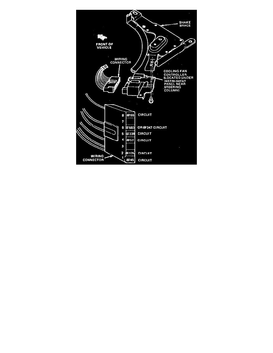
Fig. 13 Cooling fan controller terminal identification. Types 5, 6 & 7
Fan Motor Inoperative
1.
Check cooling fan fuses and fusible link. If fuses or fusible link are not blown, proceed to step 2. If fuses or fusible link are blown, repair or
replace as necessary, and retest.
2.
Disconnect fan motor electrical connector, then connect a jumper wire from motor ground connection to a known good ground and a jumper wire
from battery positive to motor B+ connection. If motor does not run, replace motor. If motor runs, reconnect electrical connector and proceed to
step 3.
3.
Disconnect coolant temperature switch connector, then connect a jumper wire from connector to ground and turn ignition ``On.'' If fan motor does
not run, proceed to step 4. If motor does run, check switch ground, and if satisfactory, replace coolant temperature switch.
4.
Turn ignition ``Off,'' then remove jumper wire installed in step 3. Using an ohmmeter, check continuity of circuit 45 from cooling fan controller
terminal #1 to coolant temperature switch. The controller, Fig. 13, is located under the instrument panel. If continuity does not exist, check wire
circuit 45 for opens. If continuity does exist, jump coolant temperature switch to ground and proceed to step 5.
5.
Without disconnecting wiring connector from controller, Fig. 13, connect battery positive to circuit 68 at controller (terminal #8). If fan motor
runs, check ignition feed circuits for opens. If fan motor does not run, remove jumper wire and proceed to step 6.
6.
Disconnect cooling fan wiring connector at controller, Fig. 13. Using a jumper wire, connect battery positive current to circuit 228 (terminal #5).
If fan motor does not run, check circuit 228 for opens. If motor runs, remove jumper and proceed to step 7.
7.
Using a jumper wire, connect circuit 175 to 228 (terminals #2 and 5) at the cooling fan motor controller connector. If motor does not run, check
circuit 175 for opens. If motor does run, replace cooling fan controller, then remove jumper wire from temperature switch and reconnect
connector.
Fan Motor Operates When Engine Overheats, Does Not Operate With A/C On
1.
Set A/C controls selector lever in A/C position and turn ignition ``On.'' If A/C clutch does not engage, proceed to step 2. If A/C clutch does
engage, proceed to step 7.
2.
Check fuse in fuse panel. If blown, replace. If fuse is not blown, proceed to step 3.
3.
Disconnect A/C clutch cycle pressure switch. Use a jumper wire to jump across connector. If A/C clutch does not engage, proceed to step 5. If A/C
clutch does engage, proceed to step 4.
4.
Check A/C system for low refrigerant charge. If charge is insufficient, leak test, service and charge system. If charge is satisfactory, replace clutch
cycling pressure switch.
5.
Using a test light, check for voltage on 348 circuit at clutch cycling pressure switch. If there is no voltage, proceed to step 6. If there is voltage,
repair open 347 circuit to A/C clutch.
6.
Using a test light, test for voltage on 296 and 348 circuits at A/C function selector switch in instrument panel. If there is voltage on 296 but not on
348, replace A/C control assembly. If there is no voltage on 296 circuit, trace circuits 296 and 297 toward ignition switch.