
LTD Country Squire V8-302 5.0L VIN F TBI (1983)
Ignition Control Module: Description and Operation
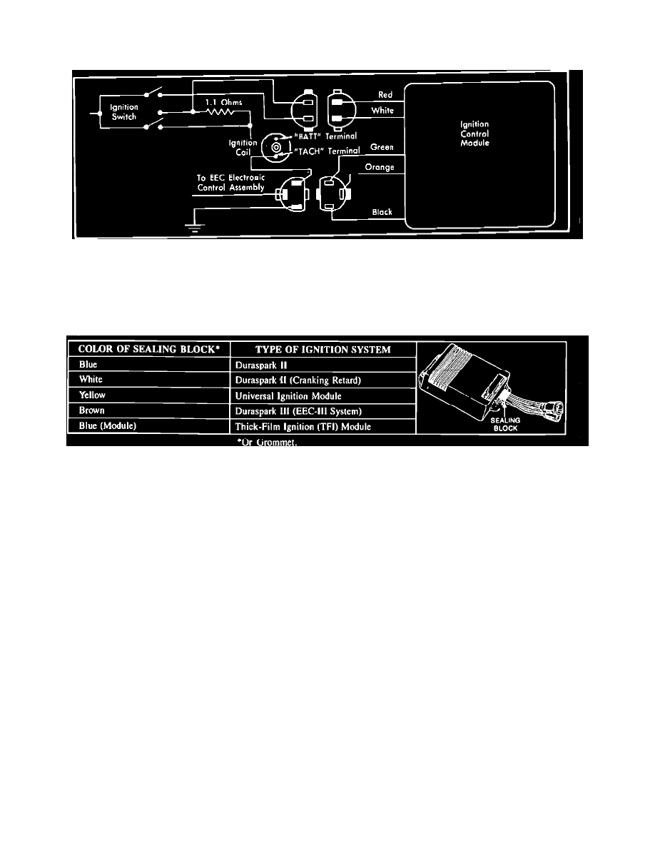
DS III
Ignition System Schematic
The Ignition Module shuts off the primary circuit each time it receives a pulse from the EEC III Microprocessor Fig. 2. A timing circuit in the ignition
module turns the primary current back on after a short period of time. High voltage is created each time the magnetic field is built up and collapsed. The
red ignition module wire provides operating voltage for the module's electronic components in the Run mode. The white module wire and start bypass
provide increased voltage for the module and coil during Start mode.
Module Identification Chart
For proper ignition module identification refer to Fig. 1. The modules are not interchangeable, Dura Spark II has 6 wire connector while Dura Spark III
has a 5 wire connector.