| In-vehicle Repair Materials Name Specification Cable ties Removal | | -
General Notes. - The positions of the engine mountings are described looking from the transmission towards the engine.
- Owing to special model variants, some job steps do not apply to all vehicles. These are clearly marked in the text.
| | | -
Standard preparatory measures - Make a note of the radio keycode.
- Make a note of the preset radio stations.
| | | -
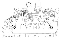
Remove the intake pipe. - Pull out the plug of the mass air flow sensor (MAF sensor).
- Disconnect the intake air temperature (IAT) sensor multiplug.
- Remove the bolt and the two nuts.
- Open the clips.
| | | -
Detach the engine undershield (nine bolts). | | | -
Detach the right-hand front wheelhouse cover. | | | -
Remove the drive belt. - Slacken the drive belt.
- Remove the drive belt.
| | | -
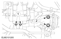
Detach the generator at the bottom. | | | -
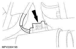
Detach the brake booster vacuum pipe from the intake manifold. - Unlock the quick-release coupling and disconnect the pipe.
- Disconnect the PCV hose from the intake manifold.
| | | -
CAUTION:Insert the wooden block between the oil pan and the trolley jack. Lift the engine with the trolley jack to take the weight off the front engine mounting. | | | -
NOTE:Mark the position of the front engine mounting bracket in relation to the power steering pump bracket. Detach the front engine mounting bracket. | | | -
Disconnect the vacuum hoses from the intake manifold. | | | -
Pull out the plug of the cylinder head wiring harness and detach the engine wiring harness from the intake manifold. - Plug.
- Wiring harness.
| | | -
Detach the accelerator cable. - Pull off the plastic clip and lay the accelerator cable to one side.
| | | -
Detach the generator and lay it to one side. | | | -
Detach the exhaust gas recirculation (EGR valve) system. - EGR pipe
- EGR valve
| | | -
Detach the EGR line bracket. | | | -
Detach the throttle position sensor (TP) multiplug. | | | -
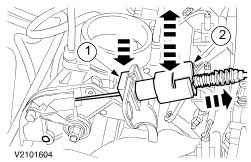
Remove the throttle housing. | | | -
Disconnect the camshaft position (CMP) sensor multiplug. | | | -
WARNING:Escaping fuel. Observe the safety regulations when handling fuel. Disconnect the fuel pipes. - Detach the fuel line bracket from the intake manifold.
| | | -
Disconnect the fuel injector plug. | | | -
Disconnect the idle air control (IAC) valve connector. | | | -
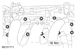
Remove the intake manifold (eight bolts, two nuts). - Detach the injector wiring harness (two bolts).
| Installation | | -
NOTE:Only use a new gasket when the old is faulty. Install the intake manifold (eight bolts, two nuts). - Attach the injector wiring harness (two bolts).
| | | -
Connect the idle air control (IAC) valve connector. | | | -
Push on the fuel injector connector. | | | -
NOTE:The pipes are marked. Connect the fuel pipes. - Attach the fuel pipe bracket to the intake manifold.
| | | -
Connect the CMP sensor plug. | | | -
Install the throttle housing with a new gasket. | | | -
Connect the TP sensor multiplug. | | | -
Install the EGR system. - EGR Valve
- EGR pipe
| | | -
Attach the bracket to the EGR line. | | | -
Install the accelerator cable and adjust it. - Install the cable in the bracket and slide on the plastic clip.
- Pull the clip off the accelerator cable.
- Pull the inner cable a few clicks out from the outer cable.
- Fully depress the accelerator pedal once and slide the clip back on.
- Check that the throttle plate opens fully when the accelerator pedal is depressed. If not, repeat the adjustment procedure.
| | | -
Attach the engine wiring harness to the intake manifold and connect the plug of the cylinder head wiring harness. - Wiring harness.
- Plugs.
| | | -
Connect the vacuum hoses to the intake manifold. | | | -
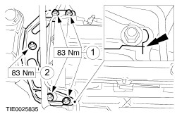
NOTE:Use new self-locking nuts. NOTE:The markings on the front engine mounting bracket and power steering pump bracket must line up. Install the front engine mounting bracket. - Tighten four nuts.
- Tighten the nut on the engine mounting.
| | | -
NOTE:Engage the vacuum pipe properly. Attach the brake booster vacuum pipe to the intake manifold. - Guide the vacuum pipe into the quick-release coupling and lock it in place.
- Press the PCV hose into place on the intake manifold.
| | | -
Tighten the lower generator bolt. | | | -
Install the drive belt and tension it. - The diagram shows the routing of the drive belt with and without an air conditioning compressor.
| | | -
Install the right-hand front wheelhouse cover. | | | -
Attach the engine undershield (nine bolts). | | | -
Install the intake pipe. - Connect the plug of the MAF sensor.
- Connect the IAT sensor plug at the intake pipe.
- Install the bolt and the two nuts.
- Close the clips.
| | | -
Standard finishing operations. - Connect the negative lead to the battery.
- Check the fluid levels and correct as necessary.
- Check the routing of the vacuum hoses and wiring and secure them with cable ties.
- Reprogram the preset radio stations.
- Carry out a road test to enable the powertrain control module (PCM) to collect data.
- Check the fluid levels again and correct as necessary.
| | |