| Removal Special Tool(s) | | Lifting bracket, engine 21-068A | | | Radiator hose clip installation and removal tool 24-003 | General Equipment Workshop hoist Drill 4 mm bit Engine lifting eye (part no. 938F 17A084 AF) Materials Name Specification Cable ties Removal All Vehicles | | -
General notes. - The positions of the engine mountings and engine roll restrictors are described looking from the transmission towards the engine.
- Operations that do not apply to all vehicles because of special model variants are identified by a note.
- Use Special Tool 24-003 if necessary when removing coolant hoses or vent tubes.
| | | -
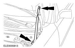
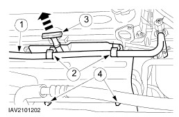
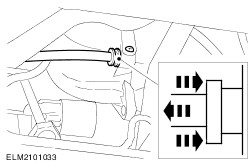
Fabricate a new auxiliary tool to keep the hood in the open position. | | | -
Open the hood and attach the auxiliary tool to it. | | | -
Standard preparatory measures - Make a note of the radio keycode.
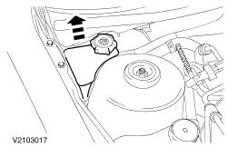
- Open up the coolant expansion tank.
- Make a note of the preset radio stations.
- Cut cable ties if necessary.
| | | -
CAUTION:Disconnect the battery negative lead. | | | -
Remove lower engine shroud (if present). | | | -
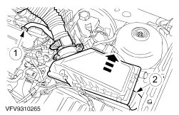
Remove the intake pipe with air cleaner housing. - Pull out the plug of the mass air flow (MAF) sensor.
- Pull out the plug of the intake air temperature sensor (IAT sensor).
- Undo the bolt and the two nuts.
| | | -
Remove the intake pipe with air cleaner housing (continued). - Remove crankcase venting hose (PCV).
- Detach the intake hose.
- Remove the air cleaner housing from the rubber ring.
| | | -
NOTE:This step only applies to vehicles with liquid propane gas (LPG) operation. | | | -
NOTE:This step only applies to vehicles with liquid propane gas (LPG) operation. Detach the bracket for the power steering line from the cylinder head. | | | -
NOTE:This step only applies to vehicles with liquid propane gas (LPG) operation. Install the engine lifting eye in place of the bracket for the power steering line. | | | -
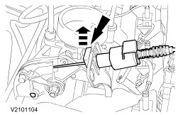
Detach the accelerator cable. - Pull off the plastic clip and lay the accelerator cable to one side.
| | | -
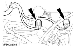
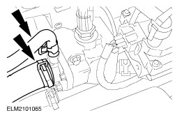
Disconnect engine wiring loom and transmission control module connector. - Undo screw and remove connector.
- Remove transmission control module connector.
| | | -
WARNING:Fuel will escape. Observe the safety precautions when dealing with fuel. Disconnect the fuel pipes. | | | -
Empty power-assisted steering reservoir using manual pump, pull out of holder and place on its side. | | | -
Remove powertrain control module (PCM) cover. | | | -
Remove engine wiring loom. - Detach the ground cable.
- Undo the screw.
- Remove connector from PCM.
| | | -
Remove connector, ground lead and pressure pipe holder. - Pull out the plug of the power steering pressure switch (PSP switch).
- Remove ground cable and power-assisted steering pressure pipe holder from engine lifting eye.
- Unclip cable from heated oxygen sensor (HO2S).
- Remove power-assisted steering pressure pipe bracket.
| | | -
Pull off exhaust gas recirculation system (EGR system) vacuum hoses. | | | -
Pull vacuum hose from intake manifold. | | | -
Disconnect the coolant hoses from the thermostat housing. | Vehicles with air conditioning | | -
Detach the bracket of the air conditioning pipe. | All vehicles | | -
Undo the starter motor upper bolts. | | | -
Remove the upper flange bolts. | Vehicles with 2,0 engine | | -
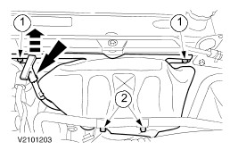
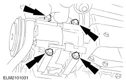
Remove the heat shield. - Detach the coolant hose from the bracket.
- Undo the upper bolts and remove the coolant hose bracket.
- Withdraw the engine oil dipstick.
- Remove the lower bolts.
| All vehicles | | -
Remove the heat shield. - Undo the upper bolts.
- Remove the lower bolts.
- Withdraw the oil dipstick.
| Vehicles with 2,0 engine | | -
Remove catalytic converter from exhaust manifold. | | | -
Remove catalytic converter from exhaust manifold. | | | -
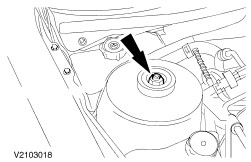
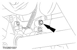
NOTE:Prevent the piston rod from moving using an Allen key. Undo nut on right-hand suspension strut five turns. | | | -
Remove coolant expansion tank. | | | -
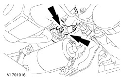
Remove the catalytic converter. - Unscrew the bolts.
- Unhook it from the rubber mountings.
| | | -
Disconnect the multiplug from the transmission speed (TSS) sensor. | | | -
Disconnect the starter motor. | | | -
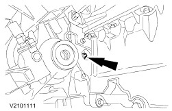
Unscrew the starter motor lower bolt and remove the starter motor. | | | -
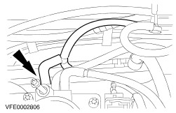
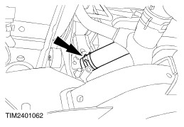
Detach the brake booster vacuum pipe from the intake manifold. - Undo the quick-release fastener and pull out the pipe.
| | | -
Detach the right-hand lower wheel arch trim panel. - Undo one bolt from the upper wheel arch trim panel.
| | | -
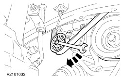
Slacken and remove the drive belt. | | | -
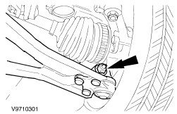
CAUTION:Do not damage gaiter and front ABS sensor ring. Remove lower right-hand suspension arm. | | | -
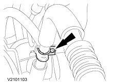
CAUTION:The maximum bending angle of the inner joint is 18 degrees, and 45 degrees for the outer joint. Remove right-hand front wheel drive shaft from intermediate shaft and remove heat shield from centre bearing bracket. | | | -
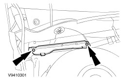
Remove brace and centre bearing bracket from engine. | | | -
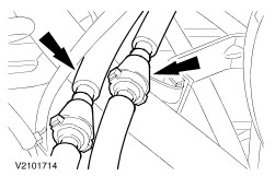
Remove coolant hoses and coolant pipe bracket. - Coolant hose from coolant pipe.
- Coolant hose from radiator.
- Coolant pipe bracket from sump.
| Vehicles with air conditioning | | -
Remove air conditioning system compressor and secure. - Lower the air conditioning compressor a little and remove magnetic clutch connector.
| All vehicles | | -
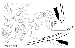
Undo torque converter (shown without intermediate shaft). - Remove rubber plug and unscrew four nuts.
| | | -
Remove the flange bolts on the left-hand side of the transmission. | | | -
Unscrew flange bolts from right-hand side of transmission (shown without intermediate shaft). | | | -
Remove coolant hose from coolant pump. | | | -
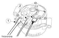
Disconnect generator and remove (shown on removed generator). - Unscrew nut and disconnect cable.
- Pull out the plugs.
| | | -
NOTE:Mark the installation position of the front engine mounting bracket. Marking points: front engine bearing bracket and power-assisted steering pump bracket. Remove the front engine support bracket. | | | -
Remove front engine bearing. | | | -
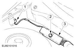
CAUTION:No hydraulic fluid must come into contact with the drive belt. NOTE:Lift the engine a little in order to remove the high pressure line. NOTE:Collect hydraulic fluid in a suitable container. Remove pipe and hose from power-assisted steering pump. - Low pressure hose
- High pressure hose
| |