| Removal Special Tool(s) | | Lifting bracket, engine 303-12 (21-068A) | | | Separator, fuel pipe 3/8" (yellow) 310-D004 (23-039) | | | Separator, fuel pipe 1/2" (green) 310-D005 (23-040) | | | Adjusting tool, gear shift mechanism - neutral position 308-273 (16-088A) | | | Radiator hose clamp remover/installer 303-397 (24-003) | General Equipment Workshop hoist Drill 4 mm drill bit Removal All Vehicles | | -
General - The positions of the engine mountings and engine roll restrictors are described looking from the transmission towards the engine.
- Sub-operations for particular variants which do not apply to all vehicles are marked clearly with a note.
- Use Special Tool 303-397 as required when disconnecting coolant or ventilation hoses.
| | | -
Make the auxiliary tool to hold the hood in the open position. | | | -
Open the hood and attach the auxiliary tool to the hood. | | | -
Standard preparatory measures. - Make a note of the radio keycode.
- Open up the coolant recovery tank.
- Make a note of the pre-set radio stations.
- Cut cable ties as necessary.
| WARNING:Disconnect the battery and remove. | | -
Unclip the gear lever boot. | | | -
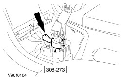
Secure the gear lever in neutral using the special tool. | | | -
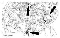
Remove the air cleaner housing. - Two positive crankcase ventilation (PCV) hoses
- Hose clamp at the throttle housing
- Idle control valve vacuum hose
- MAF multiplug
- Intake air temperature (IAT) sensor plug.
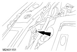
- Pull off the brake booster vacuum line from the upper intake manifold.
| | | -
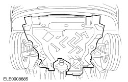
Detach the engine undershield (if equipped). | | | -
Disconnect the coolant hose from the radiator. | | | -
Drain off the transmission fluid. - Screw the drain plug back in again.
| | | -
Detach the accelerator cable (illustration shows vehicle equipped with traction control system). - Turn the cable pulley and unhook the cable.
- Pull off the clip and pull the accelerator cable out of the bracket.
| | | -
Detach the cruise control actuation cable from the throttle valve lever. | | | -
Disconnect the vacuum hose for the evaporative emission system. | | | -
Detach the bracket for the cables. | | | -
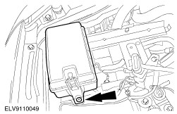
Detach the central junction box (CJB) and lay it to one side. | | | -
Remove the battery console. | | | -
Disconnect the starter motor. | | | -
Disconnect the starter motor positive lead. - Open the wiring casing and press out the positive cable.
| | | -
Drain the brake fluid reservoir using a manual suction pump. | | | -
NOTE:Close off the openings using plugs. Disconnect the line from the clutch slave cylinder. | | | -
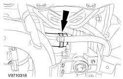
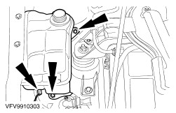
Detach the coolant hoses. | | | -
Remove the coolant recovery tank. - Disconnect the plug from the coolant level switch (if equipped).
| | | -
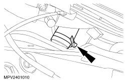
Detach/disconnect the coolant hoses. | | | -
Disconnect the coolant hose from the radiator. | | | -
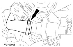
Detach the coolant hose for the distribution pipe from the thermostat housing. | | | -
NOTE:The nuts do not need to be renewed Undo the left and right-hand suspension strut nuts five turns (right-hand side shown). | Vehicles with air conditioning | | -
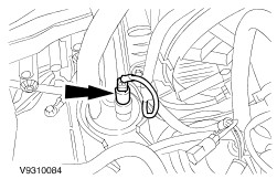
Disconnect the plug from the air conditioning collector/dehydrator. | All vehicles | | -
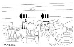
Disconnect the two fan motor plugs. - Unclip the plugs and wiring harness.
| | | -
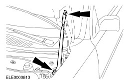
Detach the fan motor ground cable from the body. | | | -
Detach the fan from the radiator. | | | -
Detach the fan from the radiator. | | | -
Pull off the heater vacuum hoses. | | | -
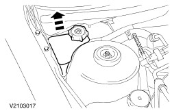
Drain the power steering fluid reservoir using the manual suction pump, pull it out (push fit) and lay it to one side. | | | -
CAUTION:Do not damage the power steering return line. Remove the cover from the powertrain control module (PCM). - Drill out the rivets (4 mm).
| | | -
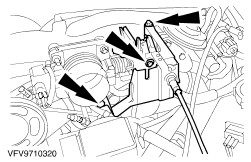
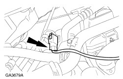
Detach the connector from the PCM and the ground cable from the body. - Disconnect the engine wiring harness from the bulkhead.
| | | -
CAUTION:No hydraulic fluid should come into contact with the drivebelt. NOTE:Collect the hydraulic fluid in a suitable container. Detach the power steering line. - Disconnect the plug.
- Power steering return line.
- Power steering high-pressure line and bracket with ground cable.
| | | -
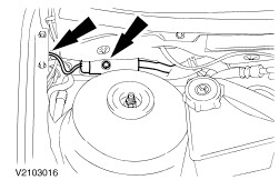
Detach the two ground cables from the transmission and detach the main wiring harness connector (one bolt). | | | -
Detach the gearshift cables from the transmission. - Detach the shift cable and the selector cable.
- Unscrew the nuts.
- Take off the bracket and lay it to one side.
| | | -
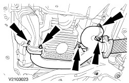
Detach the front exhaust pipe. | | | -
Remove the front exhaust pipe and catalytic converter. - Unhook the catalytic converter from the rubber loop.
| | | -
Detach the right-hand lower wheel arch trim panel (shown with the wheel removed). - Loosen the upper wheel arch trim panel.
| | | -
CAUTION:Do not damage the boot or the front ABS toothed sensor wheel. Detach the lower suspension arm on both sides (right-hand side shown). | | | -
CAUTION:The inner joint must not be bent more than 18 degrees, the outer joint not more than 45 degrees. NOTE:Tie up the front driveshaft. Remove the right-hand front driveshaft. - Pull the spindle carrier outwards and pull the front driveshaft off the intermediate shaft.
| | | -
CAUTION:The inner joint must not be bent more than 18 degrees, the outer joint not more than 45 degrees. NOTE:Tie up the front driveshaft. Remove the left-hand front driveshaft. - Pull the spindle carrier outwards and pull the front driveshaft out of the transmission.
| Vehicles with air conditioning | | -
Detach the air conditioning condenser from the radiator. - One bolt on each side (right-hand side shown).
| All vehicles Vehicles with air conditioning | | -
Disconnect the plug from the air conditioning compressor. | All vehicles | | -
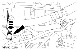
Disconnect the plug for the left-hand heated oxygen sensor (HO2S). | | | -
Detach the thermostat housing distribution pipe. | Vehicles with air conditioning | | -
Remove the heat shield from the air conditioning compressor. | Vehicles with air conditioning | | -
Detach the air conditioning compressor and tie it up. | All vehicles | | -
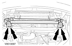
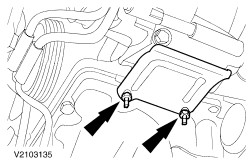
Remove the left-hand engine roll restrictor. | | | -
Remove the right-hand engine roll restrictor. - Center bolt
- Three bolts.
- Engine roll restrictor
| | | -
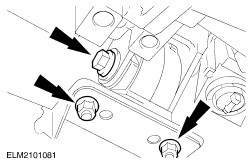
Detach the bracket for the right-hand engine roll restrictor. | | | -
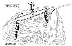
Hook the engine and manual transmission assembly into the workshop hoist and secure it. | | | -
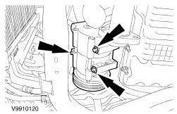
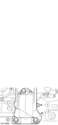
Detach the front engine mounting. | | | -
Detach the rear engine mounting. | | | -
Lift out the engine and manual transmission assembly. | |