| PINPOINT TEST B : ENGINE DOES NOT CRANK AND RELAY DOES NOT CLICK |
| TEST CONDITIONS | DETAILS/RESULTS/ACTIONS |
| B1: CHECK CONDITION OF PASSIVE ANTI-THEFT SYSTEM (PATS) SYSTEM |
| | 1 Observe the PATS warning indicator. |
| | Does the indicator flash when attempting to start the vehicle? Yes No |
| B2: CHECK OPERATION OF STARTER RELAY |
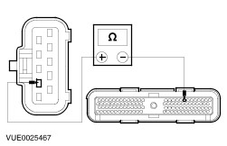
| | 1 Disconnect Starter Relay C52. |
| | 2 Carry out the relay component test. REFER to wiring diagrams. |
| | Is the relay OK? Yes No INSTALL a new starter relay. TEST the system for normal operation. |
| B3: CHECK THE BATTERY CONDITION |
| | 1 |
| | Is the battery OK? Yes No INSTALL a new battery. TEST the system for normal operation. |
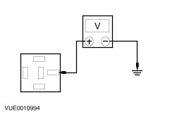
| B4: CHECK SWITCHED POWER TO THE STARTER RELAY |
| | 1 Ignition switch in position II. |
| | 2 Measure the voltage between the starter relay C52 pin 2, circuit 50-BB11 (GY/WH), harness side and ground. |
| | Is the voltage greater than 10 volts? Yes Vehicles with a zetec engine and manual transaxle (without PATS) GO to B9. . Vehicles with a zetec or duratec engine and manual transaxle (with PATS) GO to B10. . Vehicles with zetec or duratec engine and automatic transaxle (with internal PATS) GO to B13. . Vehicles with diesel engine (with PATS) GO to B17. . Vehicles with diesel engine (without PATS) GO to B18. . No |
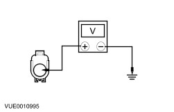
| B5: CHECK SWITCHED POWER TO THE STARTER RELAY DIODE |
| | 1 Ignition switch in position 0. |
| | 2 Disconnect Starter Relay Diode C61. |
| | 3 Ignition switch in position II. |
| | 4 Measure the voltage between starter relay diode electrical C61 circuit 50-BB11 (GY/WH), harness side and ground. |
| | Is the voltage greater than 10 volts? Yes No |
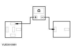
| B6: CHECK CIRCUIT 50-BB11A (GY/WH) FOR OPEN |
| | 1 Ignition switch in position 0. |
| | 2 Measure the resistance between starter relay diode C61, circuit 50-BB11A (GY/WH), harness side and the starter relay C52 pin 1, circuit 50-BB11A (GY/WH), harness side. |
| | Is the resistance less than 5 ohms? Yes INSTALL a new starter relay diode. TEST the system for normal operation. No REPAIR the circuit. TEST the system for normal operation. |
| B7: CHECK CIRCUIT 50-BB11 (GY/WH) FOR OPEN |
| | 1 Ignition switch in position 0. |
| | 2 Disconnect Ignition Switch C456. |
| | 3 Measure the resistance between the starter relay diode C61, circuit 50-BB11 (GY/WH), harness side and the ignition switch C456 pin 5, circuit 50-BB11 (GY/WH), harness side. |
| | Is the resistance less than 5 ohms? Yes No REPAIR the circuit. TEST the system for normal operation. |
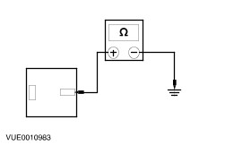
| B8: CHECK CIRCUIT 50-BB11 (GY/WH) FOR SHORT TO GROUND |
| | 1 Measure the resistance between the starter relay diode C61, circuit 50-BB11 (GY/WH), harness side and ground. |
| | Is the resistance greater than 10,000 ohms? Yes No REPAIR the circuit. TEST the system for normal operation. |
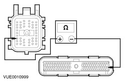
| B9: CHECK CIRCUITS 31S-BB12 (BK/YE) AND 91-BB12 (BK/YE) FOR OPEN (ZETEC WITHOUT PATS) |
| | 1 Ignition switch in position 0. |
| | 2 Disconnect In-line Connector C3001. |
| | 3 Measure the resistance between the starter relay C52 pin 1, 31S-BB12 (BK/YE), harness side and in-line connector C3001 male pin 31, circuit 31S-BB12 (BK/YE), harness side. |
| | Is the resistance less than 5 ohms ? Yes REPAIR circuit 91-BB12 (BK/YE). TEST system for normal operation. No REPAIR circuit 31S-BB12 (BK/YE). Test system for normal operation |
| B10: CHECK CIRCUIT 31S-BB12 (BK/YE) FOR OPEN (ZETEC WITH PATS) |
| | 1 Ignition switch in position 0. |
| | 2 Disconnect In-line Connector C3001. |
| | 3 Measure the resistance between the starter relay C52 pin 1, 31S-BB12 (BK/YE), harness side and in-line connector C3001 male pin 31, circuit 31S-BB12 (BK/YE), harness side. |
| | Is the resistance less than 5 ohms ? Yes Vehicles with a zetec engine and manual transaxle (with PATS) GO to B11. . Vehicles with a duratec engine and manual transaxle (with PATS) GO to B12. . Vehicles with a zetec or duratec engine and automatic transaxle (with PATS) REPAIR circuit 31S-BB12 between C3001 female pin 36 and C438 pin 4. No REPAIR circuit 31S-BB12 (BK-YE) between C52 pin 1 and C3001 male pin 31. Test system for normal operation |
| B11: CHECK CIRCUIT 31S-BB12 (BK/YE) FOR OPEN (ZETEC ENGINE MANUAL TRANSAXLE WITH PATS) |
| | 1 Disconnect Powertrain Control Module (PCM) C421. |
| | 2 Measure the resistance between in-line connector C3001 female pin 31, circuit 31S-BB12 (BK/YE) and the powertrain control module (PCM) C421 pin 27, circuit 31S-BB12 (BK/YE), harness side. |
| | Is the resistance less than 5 ohms? Yes REFER to WDS/FDS 2000. TEST the PCM. TEST the system for normal operation. No REPAIR circuit 31S-BB12 (BK/YE), between C3001 female pin 31 and C421 pin 27. TEST the system for normal operation. |
| B12: CHECK CIRCUIT 31S-BB12 (BK/YE) FOR OPEN (DURATEC ENGINE MANUAL TRANSAXLE WITH PATS) |
| | 1 Disconnect Powertrain Control Module (PCM) C421. |
| | 2 Measure the resistance between C3001 female pin 31, circuit 31S-BB12 (BK/YE), and the PCM C421 pin 18, circuit 31S-BB12 (BK/YE), harness side. |
| | Is the resistance less than 5 ohms? Yes REFER to WDS/FDS 2000. TEST the PCM. TEST the system for normal operation. No REPAIR circuit 31S-BB12 (BK/YE) between C3001 female pin 31 and C421 pin 18. TEST the system for normal operation. |
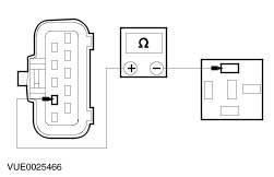
| B13: CHECK AUTOMATIC TRANSMISSON RANGE (TR) SENSOR FOR OPEN |
| | 1 Place the transaxle shift selector into the "P" position. |
| | 2 Ignition switch in position 0. |
| | 3 Disconnect Transmisson Range (TR) Sensor C438. |
| | 4 Measure the resistance of the transmission range (TR) sensor C438 between pins 4 and 9, component side. |
| | Is the resistance less than 5 ohms? Yes No |
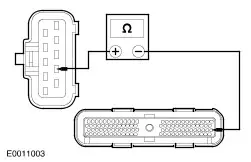
| B14: CHECK CIRCUIT 31S-BB12 (BK/YE) FOR OPEN |
| | 1 Measure the resistance between the TR sensor C438 pin 4, circuit 31S-BB12 (BK/YE), and the starter relay C52 pin 1, circuit 31S-BB12 (BK/YE), harness side. |
| | Is the resistance less than 5 ohms? Yes No Vehicles with zetec engine and automatic transaxle (with PATS) GO to B15. . Vehicles with duratec engine and automatic transaxle (with PATS) GO to B16. . |
| B15: CHECK CIRCUIT 31S-TA9 (BK/GN) FOR OPEN (ZETEC ENGINE AND AUTOMATIC TRANSAXLE WITH PATS) |
| | 1 Measure the resistance between the TR sensor C438 pin 9, circuit 31S-TA9 (BK/GN), harness side and the PCM C421 pin 27, circuit 31S-TA9 (BK/GN), harness side. |
| | Is the resistance less than 5 ohms? Yes REFER to WDS/FDS 2000. TEST the PCM. TEST the system for normal operation. No REPAIR circuit 31S-TA9 (BK/GN) between TR sensor C438 pin 9 and the PCM C421 pin 27. |
| B16: CHECK CIRCUIT 31S-TA9 (BK/GN) FOR OPEN (DURATEC ENGINE AND AUTOMATIC TRANSAXLE WITH PATS) |
| | 1 Measure the resistance between the TR sensor C438 pin 9, circuit 31S-TA9 (BK/GN), harness side and the PCM C421 pin 18, circuit 31S-TA9 (BK/GN), harness side. |
| | Is the resistance less than 5 ohms? Yes REFER to WDS/FDS 2000. TEST the PCM. TEST the system for normal operation. No REPAIR circuit 31S-TA9 (BK/GN) between TR sensor C438 pin 9 and the PCM C421 pin 18. |
| B17: CHECK CIRCUITS 31-PF9 (BK) AND 91-MB36 (BK/BU) FOR OPEN (VEHICLES WITH DIESEL ENGINE AND PATS) |
| | 1 Ignition switch in position 0. |
| | 2 Disconnect PATS Module C1944. |
| | 3 Using a fused jumper wire, connect the PATS module C1944 pin 9, circuit 31-PF9 (BK), harness side to C1944 pin 14, circuit 91-MB36 (BK/BU), harness side. |
| | 4 Measure the resistance between the starter relay C52 pin 1, circuit 31S-BB12 (BK/YE), harness side and ground. |
| | Is the resistance less than 5 ohms? Yes No |
| B18: CHECK CIRCUITS 31-PF9 (BK) AND 91-MB36 (BK/BU) FOR OPEN |
| | 1 Disconnect In-line Connector C1889. |
| | 2 Using a fused jumper wire, connect in-line connector C1889 pin 11, circuit 31-TA9 (BK), harness side and the in-line connector C1889 pin 3, circuit 91-MB36 (BK/BU), harness side. |
| | 3 Measure the resistance between the starter relay C52 pin 1, harness side and ground. |
| | Is the resistance less than 5 ohms? Yes REPAIR circuit C1994 31-PF9 (BK) or circuit 91-MB36 (BK/BU). TEST system for normal operation. REPAIR between C1899 pin 11 and C1889 pin 3, circuit 31-PF9 (BK). TEST the system for normal operation. No |
| B19: CHECK CIRCUITS 31-TA9 (BK) AND 31S-BB12 (BK/YE) FOR OPEN |
| | 1 Disconnect In-line Connector C141. |
| | 2 Measure the resistance between the starter relay C52 pin 1, harness side and in-line connector C141 pin 12, circuit 31S-BB12 (BK/YE), harness side. |
| | Is the resistance less than 5 ohms? Yes REPAIR circuit 31-TA9 (BK). TEST the system for normal operation. No REPAIR the circuit. TEST the system for normal operation. |