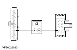
| Diagnosis and Testing Refer to Wiring Diagrams Section 412-00, for schematic and connector information. Vacuum system 1 - Air conditioning - recirculating air/fresh air - solenoid valve 2 - Vacuum actuator - floor level/headroom vents 3 - Vacuum actuator - demister nozzles 6 - Vacuum actuator - recirculating air/fresh air flap 8 - Vacuum feed from engine Inspection and Verification - Verify the customer concern.
- Visually inspect for the following mechanical and electrical causes of the concern.
Visual Inspection Chart | Mechanical | Electrical | - Vacuum line(s).
- Fan motor - passenger compartment temperature sensor.
- Drive belt.
- Fan motor(s).
| - Fuse(s)
- Wiring harness.
- Plugs
| - If the visual inspection reveals a concern, carry out repairs before proceeding with the subsequent steps.
- If the concern persists after visual inspection, proceed using the following symptom chart.
On-board diagnostics (only possible in vehicles with SATC) CAUTION:Do not perform on-board diagnostics when the temperature is set to HI. If the temperature is set to HI, select another temperature and wait approx. 30 seconds before performing on-board diagnostics. - The vehicle ambient temperature must be at least 10°C.
- Note down all the displayed diagnostic trouble codes (DTC) to be on the safe side.
Diagnostic trouble codes - On-board Diagnostics (SATC) | Diagnostic trouble codes (permanent) | Diagnostic trouble codes (sporadic) | Description of fault | Subsequent test | | 20 | 22 | Short in heater flap motor circuit | GO to Pinpoint Test ??. | | 24 | 25 | Heater flap motor control fault | GO to Pinpoint Test ??. | | 30 | - | Short in interior temperature sensor circuit | GO to Pinpoint Test ??. | | 31 | - | High resistance in interior temperature sensor circuit | GO to Pinpoint Test ??. | | 40 | 42 | Short in ambient temperature sensor circuit | GO to Pinpoint Test ??. | | 41 | 43 | High resistance in ambient temperature sensor circuit | GO to Pinpoint Test ??. | | 50 | 52 | Short in sun load sensor circuit | GO to Pinpoint Test ??. | | 60 | 62 | Fault in interior temperature sensor blower circuit | GO to Pinpoint Test ??. | | 70 | 72 | Short in engine coolant temperature pickup circuit (air conditioning) | GO to Pinpoint Test ??. | | 71 | 73 | High resistance in engine coolant temperature pickup circuit (air conditioning) | GO to Pinpoint Test ??. | Symptom Chart Symptom Chart | Symptom | Possible Sources | Action | | SATC control assembly not operational | * Fuse(s) * Circuit(s). * CJB * SATC module. * Heater blower relay. * Heater selector switch. | * GO to Pinpoint Test ??. | | SATC control assembly does not switch off, even though the heater selector switch is in the "OFF" position | * Circuit(s). * SATC module. * Heater selector switch. | * GO to Pinpoint Test ??. | | Heater blower motor not operational (SATC control assembly display operational) | * Circuit(s). * Heater blower control module. * Heater blower motor. * SATC module. | * GO to Pinpoint Test ??. | | Heater blower motor permanently running (vehicles with SATC only) | * Fuse * Circuit(s). * CJB * SATC module. * Heater blower control module. | * GO to Pinpoint Test ??. | | Recirculating air mode not operational (vehicles with SATC only) | * Circuit(s). * Recirculating air/fresh air flap. * Vacuum actuator - recirculating air/fresh air flap * Air conditioning - recirculating air/fresh air solenoid valve. * SATC module. * Vacuum line(s). | * GO to Pinpoint Test ??. | | Heater blower motor not operational (vehicles without SATC only) | * Fuse(s) * Circuit(s). * Heater blower motor. * Heater blower relay. * Heater selector switch. * Heater blower switch. * Heater blower resistor. | * GO to Pinpoint Test ??. | | Temperature flap not operational (vehicles without SATC only) | * Fuse * Circuit(s). * Heater flap motor. * Heater flap potentiometer. | * GO to Pinpoint Test ??. | | Air distribution always set to demist, regardless of the switch position | * Demister nozzle flap. * Vacuum actuator - demister nozzles. * Floor level/headroom vent flap. * Vacuum actuator - floor level/headroom vents. * Heater selector switch. * Vacuum line(s). | * GO to Pinpoint Test ??. | | Air conditioning not operational | * Fuse * Circuit(s). * Air conditioning compressor clutch diode. * Air conditioning clutch relay. * Air conditioning wide open throttle (WOT) relay. * Dual pressure switch. * Heater blower switch. * SATC module. * Air conditioning compressor clutch. * Powertrain control module (PCM). * Refrigerant circuit * Refrigerant quantity. | * GO to Pinpoint Test ??. | | Fan motors not operational or malfunctioning | * | * | Read out software version from the SATC module - Turn on the ignition.
- Select "AUTO blower" and "DEMIST" on the control assembly.
- Simultaneously press the "A/C" button and the red button (warm). After releasing them, press the red button (warm) again within two seconds.
- The software version is indicated on the digital display of the heater/air conditioning control assembly.
Pinpoint Test | PINPOINT TEST A : HEATER FLAP MOTOR CONTROL FAULT (DIAGNOSTIC TROUBLE CODE 20, 22, 24 OR 25) | | TEST CONDITIONS | DETAILS/RESULTS/ACTIONS | | A1: CHECK THE HEATER FLAP | | | 1 Remove the heater flap motor. | | | 2 Check the heater flap for ease of movement. | | | Does the heater flap move easily? Yes No REPAIR the heater flap. CLEAR the fault memory and CHECK operation of the system. | | A2: CHECK FOR SHORT TO GROUND IN THE CIRCUITS BETWEEN THE HEATER FLAP MOTOR AND THE SATC MODULE | | | 1 Ignition switch in position 0. | | | 2 Disconnect SATC module C82b. | | | 3 Disconnect Heater flap motor C400. | | | 4 Measure the resistance between SATC module connector C82b, circuit 8-CA40 (WH/BK) (or 8-FA40 (WH/BK) from 04/99), wiring harness side and ground. | | | 5 Measure the resistance between SATC module connector C82b, circuit 7-CA40 (YE/BK) (or 7-FA40 (YE/BK) from 04/99), wiring harness side and ground. | | | 6 Measure the resistance between SATC module connector C82b, circuit 14-CA39 (VT/BK) (or 15-FA39 (GN/BK) from 04/99), wiring harness side and ground. | | | 7 Measure the resistance between SATC module connector C82b, circuit 9-CA40 (BN/YE) (or 9-FA40 (BN/YE) from 04/99), wiring harness side and ground. | | | 8 Measure the resistance between SATC module connector C82b, circuit 31-CA39 (BK) (or 31-FA39 (BK) from 04/99), wiring harness side and ground. | | | Is a resistance of less than 10 kOhms registered following one of the measurements? Yes LOCATE and REPAIR the short to ground in the affected circuit using the wiring diagrams. CLEAR the fault memory and CHECK operation of the system. No | | A3: CHECK FOR SHORT TO VOLTAGE IN THE CIRCUITS BETWEEN THE HEATER FLAP MOTOR AND THE SATC MODULE | | | 1 Ignition switch in position II. | | | 2 Measure the voltage between SATC module connector C82b, circuit 8-CA40 (WH/BK) (or 8-FA40 (WH/BK) from 04/99), wiring harness side and ground. | | | 3 Measure the voltage between SATC module connector C82b, circuit 7-CA40 (YE/BK) (or 7-FA40 (YE/BK) from 04/99), wiring harness side and ground. | | | 4 Measure the voltage between SATC module connector C82b, circuit 14-CA39 (VT/BK) (or 15-FA39 (GN/BK) from 04/99), wiring harness side and ground. | | | 5 Measure the voltage between SATC module connector C82b, circuit 9-CA40 (BN/YE) (or 9-FA40 (BN/YE) from 04/99), wiring harness side and ground. | | | 6 Measure the voltage between SATC module connector C82b, circuit 31-CA39 (BK) (or 31-FA39 (BK) from 04/99), wiring harness side and ground. | | | Is a voltage registered following one of the measurements? Yes LOCATE and REPAIR the short to voltage in the affected circuit using the wiring diagrams. CLEAR the fault memory and CHECK operation of the system. No | | A4: CHECK FOR MUTUAL SHORT IN THE CIRCUITS BETWEEN THE HEATER FLAP MOTOR AND THE SATC MODULE | | | 1 Measure the resistance at the SATC module, connector C82b, between circuit 8-CA40 (WH/BK) (or 8-FA40 (WH/BK) from 04/99), wiring harness side and circuit 9-CA40 (BN/YE) (or 9-FA40 (BN/YE) from 04/99), wiring harness side. | | | 2 Measure the resistance at the SATC module, connector C82b, between circuit 8-CA40 (WH/BK) (or 8-FA40 (WH/BK) from 04/99), wiring harness side and circuit 7-CA40 (YE/BK) (or 7-FA40 (YE/BK) from 04/99), wiring harness side. | | | 3 Measure the resistance at the SATC module, connector C82b, between circuit 8-CA40 (WH/BK) (or 8-FA40 (WH/BK) from 04/99), wiring harness side and circuit 31-CA39 (BK) (or 31-FA39 (BK) from 04/99), wiring harness side. | | | 4 Measure the resistance at the SATC module, connector C82b, between circuit 8-CA40 (WH/BK) (or 8-FA40 (WH/BK) from 04/99), wiring harness side and circuit 14-CA39 (VT/BK) (or 15-FA39 (GN/BK) from 04/99), wiring harness side. | | | 5 Measure the resistance at the SATC module, connector C82b, between circuit 14-CA39 (VT/BK) (or 15-FA39 (GN/BK) from 04/99), wiring harness side and circuit 31-CA39 (BK) (or 31-FA39 (BK) from 04/99), wiring harness side. | | | 6 Measure the resistance at the SATC module, connector C82b, between circuit 14-CA39 (VT/BK) (or 15-FA39 (GN/BK) from 04/99), wiring harness side and circuit 9-CA40 (BN/YE) (or 9-FA40 (BN/YE) from 04/99), wiring harness side. | | | 7 Measure the resistance at the SATC module, connector C82b, between circuit 14-CA39 (VT/BK) (or 15-FA39 (GN/BK) from 04/99), wiring harness side and circuit 7-CA40 (YE/BK) (or 7-FA40 (YE/BK) from 04/99), wiring harness side. | | | 8 Measure the resistance at the SATC module, connector C82b, between circuit 31-CA39 (BK) (or 31-FA39 (BK) from 04/99), wiring harness side and circuit 7-CA40 (YE/BK) (or 7-FA40 (YE/BK) from 04/99), wiring harness side. | | | 9 Measure the resistance at the SATC module, connector C82b, between circuit 31-CA39 (BK) (or 31-FA39 (BK) from 04/99), wiring harness side and circuit 9-CA40 (BN/YE) (or 9-FA40 (BN/YE) from 04/99), wiring harness side. | | | 10 Measure the resistance at the SATC module, connector C82b, between circuit 9-CA40 (BN/YE) (or 9-FA40 (BN/YE) from 04/99), wiring harness side and circuit 7-CA40 (YE/BK) (or 7-FA40 (YE/BK) from 04/99), wiring harness side. | | | Is a resistance of more than 10 kOhms registered following all of the measurements? Yes No LOCATE and REPAIR the short between the affected circuits using the wiring diagrams. CLEAR the fault memory and CHECK operation of the system. | | A5: CHECK THE HEATER FLAP MOTOR POTENTIOMETER | | | 1 Measure the resistance at the heater flap motor, connector C400, between circuit 8-CA40 (WH/BK) (or 8-FA40 (WH/BK) from 04/99), component side and circuit 9-CA40 (BN/YE) (or 9-FA40 (BN/YE) from 04/99), component side. | | | Is a resistance of between 2 Ohms and 6 kOhms registered? Yes No RENEW the heater flap motor. CLEAR the fault memory and CHECK operation of the system. | | A6: CHECK THE HEATER FLAP MOTOR POTENTIOMETER | | | 1 Measure the resistance at the heater flap motor, connector C400, between circuit 7-CA40 (YE/BK) (or 7-FA40 (YE/BK) from 04/99), component side and circuit 9-CA40 (BN/YE) (or 9-FA40 (BN/YE) from 04/99), component side. | | | Is a resistance of 6 kOhms registered? Yes No RENEW the heater flap motor. CLEAR the fault memory and CHECK operation of the system. | | A7: CHECK THE HEATER FLAP MOTOR | | | 1 Measure the resistance at the heater flap motor, connector C400, between circuit 14-CA39 (VT/BK) (or 15-FA39 (GN/BK) from 04/99), component side and circuit 31-CA39 (BK) (or 31-FA39 (BK) from 04/99), component side. | | | Is a resistance of approx. 110 Ohms registered? Yes If diagnostic trouble code 20 or 22 is indicated: CHECK the SATC module and RENEW as necessary. CLEAR the fault memory and CHECK operation of the system. If diagnostic trouble code 24 or 25 is indicated: GO to A8. No RENEW the heater flap motor. CLEAR the fault memory and CHECK operation of the system. | | A8: CHECK FOR BREAKS IN THE CIRCUITS BETWEEN THE HEATER FLAP MOTOR AND THE SATC MODULE | | | 1 Measure the resistance between SATC module connector C82b, circuit 14-CA39 (VT/BK) (or 15-FA39 (GN/BK) from 04/99), wiring harness side and heater flap motor connector C400, circuit 14-CA39 (VT/BK) (or 15-FA39 (GN/BK) from 04/99), wiring harness side. | | | 2 Measure the resistance between SATC module connector C82b, circuit 31-CA39 (BK) (or 31-FA39 (BK) from 04/99), wiring harness side and heater flap motor connector C400, circuit 31-CA39 (BK) (or 31-FA39 (BK) from 04/99), wiring harness side. | | | 3 Measure the resistance between SATC module connector C82b, circuit 8-CA40 (WH/BK) (or 8-FA40 (WH/BK) from 04/99), wiring harness side and heater flap motor connector C400, circuit 8-CA40 (WH/BK) (or 8-FA40 (WH/BK) from 04/99), wiring harness side. | | | 4 Measure the resistance between SATC module connector C82b, circuit 9-CA40 (BN/YE) (or 9-FA40 (BN/YE) from 04/99), wiring harness side and heater flap motor connector C400, circuit 9-CA40 (BN/YE) (or 9-FA40 (BN/YE) from 04/99), wiring harness side. | | | 5 Measure the resistance between SATC module connector C82b, circuit 7-CA40 (YE/BK) (or 7-FA40 (YE/BK) from 04/99), wiring harness side and heater flap motor connector C400, circuit 7-CA40 (YE/BK) (or 7-FA40 (YE/BK) from 04/99), wiring harness side. | | | Is a resistance of less than 2 Ohms registered following all of the measurements? Yes CHECK the SATC module and RENEW as necessary. CLEAR the fault memory and CHECK operation of the system. No LOCATE and REPAIR the break in the affected circuit using the wiring diagrams. CLEAR the fault memory and CHECK operation of the system. | | PINPOINT TEST B : FAULT IN INTERIOR TEMPERATURE SENSOR CIRCUIT (DIAGNOSTIC TROUBLE CODE 30 OR 31) | NOTE:The vehicle interior temperature must be between 10°C and 40°C for the following test. | | TEST CONDITIONS | DETAILS/RESULTS/ACTIONS | | B1: CHECK THE INTERIOR TEMPERATURE SENSOR | | | 1 Ignition switch in position 0. | | | 2 Disconnect Interior temperature sensor C1861. | | | 3 Measure the resistance at the interior temperature sensor, connector C1861, between pin 1 and pin 2, component side. | | | Is a resistance of 4-20 kOhms registered? Yes Diagnostic trouble code 30 is output, i.e. there is a short in the interior temperature sensor circuit: GO to B2. Diagnostic trouble code 31 is output, i.e. there is high resistance in the interior temperature sensor circuit: GO to B4. No RENEW the interior temperature sensor. CLEAR the fault memory and CHECK operation of the system. | | B2: CHECK FOR SHORT TO GROUND IN THE CIRCUIT BETWEEN THE INTERIOR TEMPERATURE SENSOR AND THE SATC MODULE | | | 1 Disconnect SATC module C82a. | | | 2 Measure the resistance between SATC module connector C82a, circuit 8-CA48 (WH/GN) (or 8-FA48 (WH/GN) from 04/99), wiring harness side and ground. | | | Is a resistance of more than 10 kOhms registered? Yes CHECK the SATC module and RENEW as necessary. CLEAR the fault memory and CHECK operation of the system. No | | B3: CHECK FOR MUTUAL SHORT IN THE CIRCUITS BETWEEN THE INTERIOR TEMPERATURE SENSOR AND THE SATC MODULE | | | 1 Disconnect SATC module C82b. | | | 2 Measure the resistance at the SATC module between connector C82a, circuit 8-CA48 (WH/GN) (or 8-FA48 (WH/GN) from 04/99), wiring harness side and connector C82b, circuit 9-CA48A (BN/GN) (or 9-FA48A (BN/GN) from 04/99), wiring harness side. | | | Is a resistance of more than 10 kOhms registered? Yes LOCATE and REPAIR the short to ground in circuit 8-CA48 (WH/GN) (or 8-FA48 (WH/GN) from 04/99) between the interior temperature sensor and the SATC module using the wiring diagrams. CLEAR the fault memory and CHECK operation of the system. No LOCATE and REPAIR the mutual short in the circuits between the interior temperature sensor and the SATC module using the wiring diagrams. CLEAR the fault memory and CHECK operation of the system. | | B4: CHECK FOR BREAKS IN THE CIRCUIT BETWEEN THE INTERIOR TEMPERATURE SENSOR AND THE SATC MODULE | | | 1 Disconnect SATC module C82a. | | | 2 Measure the resistance between SATC module connector C82a, circuit 8-CA48 (WH/GN) (or 8-FA48 (WH/GN) from 04/99), wiring harness side and interior temperature sensor connector C1861, circuit 8-CA48 (WH/GN) (or 8-FA48 (WH/GN) from 04/99), wiring harness side. | | | Is a resistance of less than 2 Ohms registered? Yes No LOCATE and REPAIR the break in circuit 8-CA48 (WH/GN) (or 8-FA48 (WH/GN) from 04/99) between the SATC module and the interior temperature sensor using the wiring diagrams. CHECK operation of the system | | B5: CHECK FOR BREAKS IN THE CIRCUIT BETWEEN THE INTERIOR TEMPERATURE SENSOR AND THE SATC MODULE | | | 1 Disconnect SATC module C82b. | | | 2 Measure the resistance between SATC module connector C82b, circuit 9-CA48A (BN/GN) (or 9-FA48A (BN/GN) from 04/99), wiring harness side and interior temperature sensor connector C1861, circuit 9-CA48 (BN/GN) (or 9-FA48 (BN/GN) from 04/99), wiring harness side. | | | Is a resistance of less than 2 Ohms registered? Yes No LOCATE and REPAIR the break in circuit 9-CA48 (BN/GN) or 9-CA48A (BN/GN) (or 9-FA48 (BN/GN) or 9-FA48A (BN/GN) from 04/99) between the SATC module and the interior temperature sensor using the wiring diagrams. CHECK operation of the system | | B6: CHECK FOR SHORT TO VOLTAGE IN THE CIRCUIT BETWEEN THE INTERIOR TEMPERATURE SENSOR AND THE SATC MODULE | | | 1 Measure the voltage between SATC module connector C82a, circuit 8-CA48 (WH/GN) (or 8-FA48 (WH/GN) from 04/99), wiring harness side and ground. | | | Is a voltage registered? Yes LOCATE and REPAIR the short to voltage in circuit 8-CA48 (WH/GN) (or 8-FA48 (WH/GN) from 04/99) between the interior temperature sensor and the SATC module using the wiring diagrams. CLEAR the fault memory and CHECK operation of the system. No CHECK the SATC module and RENEW as necessary. CLEAR the fault memory and CHECK operation of the system. | | PINPOINT TEST C : FAULT IN AMBIENT TEMPERATURE SENSOR CIRCUIT (DIAGNOSTIC TROUBLE CODE 40, 41, 42 OR 43) | NOTE:The vehicle ambient temperature must be between 10°C and 40°C for the following test. | | TEST CONDITIONS | DETAILS/RESULTS/ACTIONS | | C1: CHECK THE AMBIENT TEMPERATURE SENSOR | | | 1 Ignition switch in position 0. | | | 2 Disconnect Ambient temperature sensor (C1863). | | | 3 Measure the resistance at ambient temperature sensor connector C1863 between pin 1 and pin 2, component side. | | | Is a resistance of 1.2-3.9 kOhms registered? Yes Diagnostic trouble code 40 or 42 is output, i.e. there is a short in the ambient temperature sensor circuit: GO to C2. Diagnostic trouble code 41 or 43 is output, i.e. there is high resistance in the ambient temperature sensor circuit: GO to C4. No RENEW the ambient temperature sensor. CLEAR the fault memory and CHECK operation of the system. | | C2: CHECK FOR SHORT TO GROUND IN THE CIRCUIT BETWEEN THE AMBIENT TEMPERATURE SENSOR AND THE SATC MODULE | | | 1 Disconnect SATC module C82a. | | | 2 Measure the resistance between SATC module connector C82a, circuit 8-CA49 (WH/VT) (or 8-FA49 (WH/VT) from 04/99), wiring harness side and ground. | | | Is a resistance of more than 10 kOhms registered? Yes CHECK the SATC module and RENEW as necessary. CLEAR the fault memory and CHECK operation of the system. No | | C3: CHECK FOR MUTUAL SHORT IN THE CIRCUITS BETWEEN THE AMBIENT TEMPERATURE SENSOR AND THE SATC MODULE | | | 1 Disconnect SATC module C82b. | | | 2 Measure the resistance at the SATC module between connector C82a, circuit 8-CA49 (WH/VT) (or 8-FA49 (WH/VT) from 04/99), wiring harness side and connector C82b, circuit 9-CA48A (BN/GN) (or 9-FA48A (BN/GN) from 04/99), wiring harness side. | | | Is a resistance of more than 10 kOhms registered? Yes LOCATE and REPAIR the short to ground in circuit 8-CA49 (WH/VT) (or 8-FA49 (WH/VT) from 04/99) between the ambient temperature sensor and the SATC module using the wiring diagrams. CLEAR the fault memory and CHECK operation of the system. No LOCATE and REPAIR the mutual short in the circuits between the ambient temperature sensor and the SATC module using the wiring diagrams. CLEAR the fault memory and CHECK operation of the system. | | C4: CHECK FOR BREAKS IN THE CIRCUIT BETWEEN THE AMBIENT TEMPERATURE SENSOR AND THE SATC MODULE | | | 1 Disconnect SATC module C82a. | | | 2 Measure the resistance between SATC module connector C82a, circuit 8-CA49 (WH/VT) (or 8-FA49 (WH/VT) from 04/99), wiring harness side and ambient temperature sensor connector C1863, circuit 8-CA49 (WH/VT) (or 8-FA49 (WH/VT) from 04/99), wiring harness side. | | | Is a resistance of less than 2 Ohms registered? Yes No LOCATE and REPAIR the break in circuit 8-CA49 (WH/VT) (or 8-FA49 (WH/VT) from 04/99) between the SATC module and the ambient temperature sensor using the wiring diagrams. CHECK operation of the system | | C5: CHECK FOR BREAKS IN THE CIRCUIT BETWEEN THE AMBIENT TEMPERATURE SENSOR AND THE SATC MODULE | | | 1 Disconnect SATC module C82b. | | | 2 Measure the resistance between SATC module connector C82b, circuit 9-CA48A (BN/GN) (or 9-FA48A (BN/GN) from 04/99), wiring harness side and ambient temperature sensor connector C1863, circuit 9-CA49 (BN/WH) (or 9-FA49 (BN/WH) from 04/99), wiring harness side. | | | Is a resistance of less than 2 Ohms registered? Yes No LOCATE and REPAIR the break in circuit 9-CA48A (BN/GN) (or 9-FA48A (BN/GN) from 04/99) or 9-CA49 (BN/WH) (or 9-FA49 (BN/WH) from 04/99) between the SATC module and the ambient temperature sensor using the wiring diagrams. CHECK operation of the system | | C6: CHECK FOR SHORT TO VOLTAGE IN THE CIRCUIT BETWEEN THE AMBIENT TEMPERATURE SENSOR AND THE SATC MODULE | | | 1 Measure the voltage between SATC module connector C82a, circuit 8-CA49 (WH/VT) (or 8-FA49 (WH/VT) from 04/99), wiring harness side and ground. | | | Is a voltage registered? Yes LOCATE and REPAIR the short to voltage in circuit 8-CA49 (WH/VT) (or 8-FA49 (WH/VT) from 04/99) between the ambient temperature sensor and the SATC module using the wiring diagrams. CLEAR the fault memory and CHECK operation of the system. No CHECK the SATC module and RENEW as necessary. CLEAR the fault memory and CHECK operation of the system. | | PINPOINT TEST D : FAULT IN SUN LOAD SENSOR CIRCUIT (DIAGNOSTIC TROUBLE CODE 50 OR 52) | | TEST CONDITIONS | DETAILS/RESULTS/ACTIONS | | D1: CHECK THE SUN LOAD SENSOR | | | 1 Disconnect Sun load sensor C1862. | | | 2 Measure the voltage at the sun load sensor, connector C1862, between pin 1 and pin 2, component side. | | | 3 Shine a light source (e.g. a torch) onto the sun load sensor. | | | Is a voltage of at least 0.2 Volts registered? Yes No RENEW the sun load sensor. CLEAR the fault memory and CHECK operation of the system. | | D2: CHECK FOR SHORT TO GROUND IN THE CIRCUIT BETWEEN THE SUN LOAD SENSOR AND THE SATC MODULE | | | 1 Disconnect SATC module C82a. | | | 2 Measure the resistance between SATC module connector C82a, circuit 8-CA53 (WH/BU) (or 8-FA53 (WH/BU) from 04/99), wiring harness side and ground. | | | Is a resistance of more than 10 kOhms registered? Yes No LOCATE and REPAIR the short to ground in circuit 8-CA53 (WH/BU) (or 8-FA53 (WH/BU) from 04/99) between the sun load sensor and the SATC module using the wiring diagrams. CLEAR the fault memory and CHECK operation of the system. | | D3: CHECK FOR SHORT TO GROUND IN THE CIRCUIT BETWEEN THE SUN LOAD SENSOR AND THE SATC MODULE | | | 1 Measure the resistance between SATC module connector C82a, circuit 9-CA53 (BN/BU) (or 9-FA53 (BN/BU) from 04/99), wiring harness side and ground. | | | Is a resistance of more than 10 kOhms registered? Yes No LOCATE and REPAIR the short to ground in circuit 9-CA53 (BN/BU) (or 9-FA53 (BN/BU) from 04/99) between the sun load sensor and the SATC module using the wiring diagrams. CLEAR the fault memory and CHECK operation of the system. | | D4: CHECK FOR MUTUAL SHORT IN THE CIRCUITS BETWEEN THE SUN LOAD SENSOR AND THE SATC MODULE | | | 1 Measure the resistance at the SATC module, connector C82a, between circuit 8-CA53 (WH/BU) (or 8-FA53 (WH/BU) from 04/99), wiring harness side and circuit 9-CA53 (BN/BU) (or 9-FA53 (BN/BU) from 04/99), wiring harness side. | | | Is a resistance of more than 10 kOhms registered? Yes No LOCATE and REPAIR the mutual short in circuits 8-CA53 (WH/BU) (or 8-FA53 (WH/BU) from 04/99) and 9-CA53 (BN/BU) (or 9-FA53 (BN/BU) from 04/99) between the sun load sensor and the SATC module using the wiring diagrams. CLEAR the fault memory and CHECK operation of the system. | | D5: CHECK FOR SHORT TO VOLTAGE IN THE CIRCUIT BETWEEN THE SUN LOAD SENSOR AND THE SATC MODULE | | | 1 Measure the voltage between SATC module connector C82a, circuit 8-CA53 (WH/BU) (or 8-FA53 (WH/BU) from 04/99), wiring harness side and ground. | | | Is a voltage registered? Yes LOCATE and REPAIR the short to voltage in circuit 8-CA53 (WH/BU) (or 8-FA53 (WH/BU) from 04/99) between the sun load sensor and the SATC module using the wiring diagrams. CLEAR the fault memory and CHECK operation of the system. No | | D6: CHECK FOR SHORT TO VOLTAGE IN THE CIRCUIT BETWEEN THE SUN LOAD SENSOR AND THE SATC MODULE | | | 1 Measure the voltage between SATC module connector C82a, circuit 9-CA53 (BN/BU) (or 9-FA53 (BN/BU) from 04/99), wiring harness side and ground. | | | Is a voltage registered? Yes LOCATE and REPAIR the short to voltage in circuit 9-CA53 (BN/BU) (or 9-FA53 (BN/BU) from 04/99) between the sun load sensor and the SATC module using the wiring diagrams. CLEAR the fault memory and CHECK operation of the system. No CHECK the SATC module and RENEW as necessary. CLEAR the fault memory and CHECK operation of the system. | | PINPOINT TEST E : FAULT IN INTERIOR TEMPERATURE SENSOR BLOWER CIRCUIT (DIAGNOSTIC TROUBLE CODE 60 OR 62) | CAUTION:The pin assignment on interior temperature sensor connector C1861 may differ from the figure illustrated in the case of some vehicles. Therefore, always pay attention to the indicated wire colours. | NOTE:The interior temperature sensor blower and the interior temperature sensor are joined together to make a single component. | | TEST CONDITIONS | DETAILS/RESULTS/ACTIONS | | E1: CHECK OPERATION OF THE INTERIOR TEMPERATURE SENSOR BLOWER | | | 1 Ignition switch in position II. | | | 2 Switch on the heater. | | | 3 Check operation of the interior temperature sensor blower. | | | Is the interior temperature sensor blower operational? Yes No | | E2: CHECK THE INTERIOR TEMPERATURE SENSOR BLOWER POWER SUPPLY VOLTAGE | | | 1 Ignition switch in position 0. | | | 2 Disconnect Interior temperature sensor C1861. | | | 3 Ignition switch in position II. | | | 4 Switch on the heater. | | | 5 Measure the voltage between interior temperature sensor connector C1861, circuit 14S-CA48 (VT/BK) (or 15S-FA48 (GN/BK) from 04/99), wiring harness side and ground. | | | Does the meter display battery voltage? Yes No REPAIR the interior temperature sensor blower power supply voltage using the wiring diagrams. CLEAR the fault memory and CHECK operation of the system. | | E3: CHECK THE INTERIOR TEMPERATURE SENSOR BLOWER GROUND CONNECTION | | | 1 Switch on the heater. | | | 2 Measure the resistance between interior temperature sensor connector C1861, circuit 31-CA48 (BK) (or 31-FA48 (BK) from 04/99), wiring harness side and ground. | | | Is a resistance of less than 2 Ohms registered? Yes RENEW the interior temperature sensor blower. CLEAR the fault memory and CHECK operation of the system. No | | E4: CHECK FOR BREAKS IN THE CIRCUIT BETWEEN THE INTERIOR TEMPERATURE SENSOR AND THE SATC MODULE | | | 1 Ignition switch in position 0. | | | 2 Disconnect SATC module C82b. | | | 3 Measure the resistance between SATC module connector C82b, circuit 31-CA48 (BK) (or 31-FA48 (BK) from 04/99), wiring harness side and interior temperature sensor connector C1861, circuit 31-CA48 (BK) (or 31-FA48 (BK) from 04/99), wiring harness side. | | | Is a resistance of less than 2 Ohms registered? Yes CHECK the SATC module and RENEW as necessary. CLEAR the fault memory and CHECK operation of the system. No LOCATE and REPAIR the break in circuit 31-CA48 (BK) (or 31-FA48 (BK) from 04/99) between the SATC module and the interior temperature sensor using the wiring diagrams. CLEAR the fault memory and CHECK operation of the system. | | E5: CHECK FOR SHORT TO GROUND IN THE CIRCUIT BETWEEN THE INTERIOR TEMPERATURE SENSOR AND THE SATC MODULE | | | 1 Ignition switch in position 0. | | | 2 Disconnect SATC module C82b. | | | 3 Disconnect Interior temperature sensor C1861. | | | 4 Measure the resistance between interior temperature sensor connector C1861, circuit 31-CA48 (BK) (or 31-FA48 (BK) from 04/99), wiring harness side and ground. | | | Is a resistance of more than 10 kOhms registered? Yes CHECK the SATC module and RENEW as necessary. CLEAR the fault memory and CHECK operation of the system. No LOCATE and REPAIR the short to ground in circuit 31-CA48 (BK) (or 31-FA48 (BK) from 04/99) using the wiring diagrams. CLEAR the fault memory and CHECK operation of the system. | | PINPOINT TEST F : FAULT IN ENGINE COOLANT TEMPERATURE PICKUP CIRCUIT (AIR CONDITIONING) (DIAGNOSTIC TROUBLE CODE 70, 71, 72 OR 74) | NOTE:For the following test, the engine coolant temperature must be between 10°C and 40°C and, if necessary, the engine coolant temperature pickup (air conditioning) must be removed and allowed to cool down sufficiently. | | TEST CONDITIONS | DETAILS/RESULTS/ACTIONS | | F1: CHECK THE ENGINE COOLANT TEMPERATURE PICKUP (AIR CONDITIONING) | | | 1 Ignition switch in position 0. | | | 2 Disconnect Engine coolant temperature pickup (air conditioning) C1864. | | | 3 Measure the resistance at the engine coolant temperature pickup (air conditioning), connector C1864, between pin 1 and pin 2, component side. | | | Is a resistance of 1.3-5.7 kOhms registered? Yes Diagnostic trouble code 70 or 72 is output, i.e. there is a short in the engine coolant temperature pickup (air conditioning) circuit: GO to F2. Diagnostic trouble code 71 or 73 is output, i.e. there is high resistance in the engine coolant temperature pickup (air conditioning) circuit: GO to F4. No RENEW the engine coolant temperature pickup (air conditioning). CLEAR the fault memory and CHECK operation of the system. | | F2: CHECK FOR SHORT TO GROUND IN THE CIRCUIT BETWEEN THE ENGINE COOLANT TEMPERATURE PICKUP (AIR CONDITIONING) AND THE SATC MODULE | | | 1 Disconnect SATC module C82a. | | | 2 Measure the resistance between SATC module connector C82a, circuit 8-CA77 (WH/BK) (or 8-FA77 (WH/BK) from 04/99), wiring harness side and ground. | | | Is a resistance of more than 10 kOhms registered? Yes CHECK the SATC module and RENEW as necessary. CLEAR the fault memory and CHECK operation of the system. No | | F3: CHECK FOR MUTUAL SHORT IN THE CIRCUITS BETWEEN THE ENGINE COOLANT TEMPERATURE PICKUP (AIR CONDITIONING) AND THE SATC MODULE | | | 1 Disconnect SATC module C82b. | | | 2 Measure the resistance at the SATC module between connector C82a, circuit 8-CA77 (WH/BK) (or 8-FA77 (WH/BK) from 04/99), wiring harness side and connector C82b, circuit 9-CA48A (BN/GN) (or 9-FA48A (BN/GN) from 04/99), wiring harness side. | | | Is a resistance of more than 10 kOhms registered? Yes LOCATE and REPAIR the short to ground in circuit 8-CA77 (WH/BK) (or 8-FA77 (WH/BK) from 04/99) between the engine coolant temperature pickup (air conditioning) and the SATC module using the wiring diagrams. CLEAR the fault memory and CHECK operation of the system. No LOCATE and REPAIR the mutual short in the circuits between the engine coolant temperature pickup (air conditioning) and the SATC module using the wiring diagrams. CLEAR the fault memory and CHECK operation of the system. | | F4: CHECK FOR BREAKS IN THE CIRCUIT BETWEEN THE ENGINE COOLANT TEMPERATURE PICKUP (AIR CONDITIONING) AND THE SATC MODULE | | | 1 Disconnect SATC module C82a. | | | 2 Measure the resistance between SATC module connector C82a, circuit 8-CA77 (WH/BK) (or 8-FA77 (WH/BK) from 04/99), wiring harness side and engine coolant temperature pickup (air conditioning) connector C1864, circuit 8-CA77 (WH/BK) (or 8-FA77 (WH/BK) from 04/99), wiring harness side. | | | Is a resistance of less than 2 Ohms registered? Yes No LOCATE and REPAIR the break in circuit 8-CA77 (WH/BK) (or 8-FA77 (WH/BK) from 04/99) between the SATC module and the engine coolant temperature pickup (air conditioning) using the wiring diagrams. CHECK operation of the system | | F5: CHECK FOR BREAKS IN THE CIRCUIT BETWEEN THE ENGINE COOLANT TEMPERATURE PICKUP (AIR CONDITIONING) AND THE SATC MODULE | | | 1 Disconnect SATC module C82b. | | | 2 Measure the resistance between SATC module connector C82b, circuit 9-CA48A (BN/GN) (or 9-FA48A (BN/GN) from 04/99), wiring harness side and engine coolant temperature pickup (air conditioning) connector C1864, circuit 9-CA77 (BN/YE) (or 9-FA77 (BN/YE) from 04/99), wiring harness side. | | | Is a resistance of less than 2 Ohms registered? Yes No LOCATE and REPAIR the break in circuit 9-CA48A (BN/GN) or 9-CA77 (BN/YE) (or 9-FA48A (BN/GN) or 9-FA77 (BN/YE) from 04/99) between the SATC module and the engine coolant temperature pickup (air conditioning) using the wiring diagrams. CHECK operation of the system | | F6: CHECK FOR SHORT TO VOLTAGE IN THE CIRCUIT BETWEEN THE ENGINE COOLANT TEMPERATURE PICKUP (AIR CONDITIONING) AND THE SATC MODULE | | | 1 Measure the voltage between SATC module connector C82a, circuit 8-CA77 (WH/BK) (or 8-FA77 (WH/BK) from 04/99), wiring harness side and ground. | | | Is a voltage registered? Yes LOCATE and REPAIR the short to voltage in circuit 8-CA77 (WH/BK) (or 8-FA77 (WH/BK) from 04/99) between the engine coolant temperature pickup (air conditioning) and the SATC module using the wiring diagrams. CLEAR the fault memory and CHECK operation of the system. No CHECK the SATC module and RENEW as necessary. CLEAR the fault memory and CHECK operation of the system. | | PINPOINT TEST G : SATC CONTROL ASSEMBLY NOT OPERATIONAL | | TEST CONDITIONS | DETAILS/RESULTS/ACTIONS | | G1: CHECK FUSE F30 (OR F23 FROM 08/99) | | | 1 CHECK Fuse F30 (or F23 from 08/99) (CJB). | | | 2 Check fuse F30 (or F23 from 08/99) (7.5 A). | | | Is fuse OK? Yes No RENEW fuse F30 (or F23 from 08/99). If the fuse blows again, LOCATE and REPAIR the short to ground using the wiring diagrams. CHECK operation of the system | | G2: CHECK THE VOLTAGE AT FUSE F30 (OR F23 FROM 08/99) | | | 1 Connect Fuse F30 (or F23 from 08/99) (CJB). | | | 2 Ignition switch in position II. | | | 3 Measure the voltage between fuse F30 (or F23 from 08/99) (7.5 A) and ground. | | | Does the meter display battery voltage? Yes No REPAIR the power supply voltage for fuse F30 (or F23 from 08/99) using the wiring diagrams, RENEW the CJB if necessary. CHECK operation of the system | | G3: CHECK FUSE F34 (OR F25 FROM 01/00) | | | 1 Ignition switch in position 0. | | | 2 CHECK Fuse F34 (or F25 from 01/00) (CJB). | | | 3 Check fuse F34 (or F25 from 01/00) (7.5 A). | | | Is fuse OK? Yes No RENEW fuse F34 (or F25 from 01/00). If the fuse blows again, LOCATE and REPAIR the short to ground using the wiring diagrams. CHECK operation of the system | | G4: CHECK THE VOLTAGE AT FUSE F34 (OR F25 FROM 01/00) | | | 1 Connect Fuse F31 (or F25 from 01/00) (CJB). | | | 2 Measure the voltage between fuse F34 (or F25 from 01/00) (7.5 A) and ground. | | | Does the meter display battery voltage? Yes No REPAIR the power supply voltage for fuse F34 (or F25 from 01/00) using the wiring diagrams, RENEW the CJB if necessary. CHECK operation of the system | | G5: CHECK FUSE F37. | | | 1 CHECK Fuse F37 (CJB). | | | 2 Check fuse F37 (30 A) | | | Is fuse OK? Yes No RENEW fuse F37. If the fuse blows again, LOCATE and REPAIR the short to ground using the wiring diagrams. CHECK operation of the system | | G6: TEST VOLTAGE AT FUSE F37 | | | 1 Connect Fuse F37 (CJB). | | | 2 Test voltage between fuse F37 (30 A) and ground. | | | Does the meter display battery voltage? Yes No REPAIR the power supply voltage for fuse F37 using the wiring diagrams, RENEW the CJB if necessary. CHECK operation of the system | | G7: CHECK THE POWER SUPPLY VOLTAGE AT THE SATC MODULE | | | 1 Ignition switch in position 0. | | | 2 Disconnect SATC module C82b. | | | 3 Ignition switch in position II. | | | 4 Measure the voltage between SATC module connector C82b, circuit 14S-CA43D (VT/WH) (or 15S-FA43D (GN/WH) from 04/99), wiring harness side and ground. | | | Does the meter display battery voltage? Yes No | | G8: CHECK THE CONTROL VOLTAGE AT THE SATC MODULE | | | 1 Switch on the heater. | | | 2 Measure the voltage between SATC module connector C82b, circuit 14S-CA27 (VT/WH) (or 15S-FA27 (GN/WH) from 04/99), wiring harness side and ground. | | | Does the meter display battery voltage? Yes No | | G9: CHECK THE POWER SUPPLY VOLTAGE AT THE SATC MODULE | | | 1 Ignition switch in position 0. | | | 2 Measure the voltage between SATC module connector C82b, circuit 29-CA43 (OG/WH) (or 29-FA43 (OG/WH) from 04/99), wiring harness side and ground. | | | Does the meter display battery voltage? Yes No LOCATE and REPAIR the break in the circuit between fuse F34 and the SATC module using the wiring diagrams. CHECK operation of the system | | G10: CHECK THE SATC MODULE GROUND CONNECTION | | | 1 Measure the resistance between SATC module connector C82b, circuit 31-CA43 (BK) (or 31-FA43 (BK) from 4/99), wiring harness side and ground. | | | Is a resistance of less than 2 Ohms registered? Yes CHECK the SATC module and RENEW as necessary. Check operation of the system No REPAIR the SATC module ground connection using the wiring diagrams. CHECK operation of the system | | G11: CHECK THE CONTROL VOLTAGE AT THE HEATER BLOWER RELAY | CAUTION:At heater blower relay socket C81, the control wires (pin 1 and pin 2) in some vehicles may be transposed. Take this into account without fail when performing the following measurement. | | | 1 Ignition switch in position 0. | | | 2 Disconnect Heater blower relay C81. | | | 3 Ignition switch in position II. | | | 4 Measure the voltage between heater blower relay socket C81, pin 2, wiring harness side and ground. | | | Does the meter display battery voltage? Yes No LOCATE and REPAIR the break in the circuit between fuse F30 (or F23 from 08/99) and the heater blower relay using the wiring diagrams. CHECK operation of the system | | G12: CHECK THE HEATER BLOWER RELAY GROUND CONNECTION | CAUTION:At heater blower relay socket C81, the control wires (pin 1 and pin 2) in some vehicles may be transposed. Take this into account without fail when performing the following measurement. | | | 1 Ignition switch in position 0. | | | 2 Measure the resistance between heater blower relay socket C81, pin 1, wiring harness side and ground. | | | Is a resistance of less than 2 Ohms registered? Yes No REPAIR the heater blower relay ground connection using the wiring diagrams. CHECK operation of the system | | G13: CHECK THE POWER SUPPLY VOLTAGE AT THE HEATER BLOWER RELAY | | | 1 Measure the voltage between heater blower relay socket C81, pin 3, wiring harness side and ground. | | | Does the meter display battery voltage? Yes No REPAIR the power supply voltage for the heater blower relay using the wiring diagrams, RENEW the CJB if necessary. CHECK operation of the system | | G14: CHECK THE HEATER BLOWER RELAY | | | 1 Connect SATC module C82b. | | | 2 Use a fused test lead (30 A) at the heater blower relay, socket C81, to short pin 3, wiring harness side and pin 5, wiring harness side. | | | 3 Ignition switch in position II. | | | 4 Switch on the heater. | | | 5 Check operation of the SATC module. | | | Is the SATC module operational? Yes RENEW the heater blower relay. CHECK operation of the system No LOCATE and REPAIR the break in circuit 14S-CA1 (VT/BU) or 14S-CA43D (VT/WH) (or 15S-FA1 (GN/BU) or 15S-FA43D (GN/WH) from 04/99) between the heater blower relay and the SATC module using the wiring diagrams. CHECK operation of the system | | G15: CHECK THE POWER SUPPLY VOLTAGE AT THE HEATER SELECTOR SWITCH | | | 1 Ignition switch in position 0. | | | 2 Disconnect Heater selector switch C82c. | | | 3 Ignition switch in position II. | | | 4 Measure the voltage at the heater selector switch, connector C82c, between circuit 14S-CA43C (VT/WH) (or 15S-FA43C (GN/WH) from 04/99), wiring harness side and ground. | | | Does the meter display battery voltage? Yes No LOCATE and REPAIR the break in circuit 14S-CA43C (VT/WH) (or 15S-FA43C (GN/WH) from 04/99) between the heater selector switch and splice S166 using the wiring diagrams. CHECK operation of the system | | G16: CHECK THE HEATER SELECTOR SWITCH | | | 1 Ignition switch in position 0. | | | 2 Use a fused test lead (30 A) at the heater selector switch, connector C82c, to short circuit 14S-CA43C (VT/WH) (or 15S-FA43C (GN/WH) from 04/99), wiring harness side and circuit 14S-CA43B (VT/WH) (or 15S-FA43B (GN/WH) from 04/99), wiring harness side. | | | 3 Ignition switch in position II. | | | 4 Check operation of the SATC module. | | | Is the SATC module operational? Yes RENEW the heater selector switch. CHECK operation of the system No LOCATE and REPAIR the break in circuit 14S-CA27 (VT/WH) (or 15S-FA27 (GN/WH) from 04/99) or 14S-CA43B (VT/WH) (or 15S-FA43B (GN/WH) from 04/99) between the heater selector switch and the SATC module using the wiring diagrams. CHECK operation of the system | | PINPOINT TEST H : SATC CONTROL ASSEMBLY DOES NOT SWITCH OFF, EVEN THOUGH THE HEATER SELECTOR SWITCH IS IN THE "OFF" POSITION | | TEST CONDITIONS | DETAILS/RESULTS/ACTIONS | | H1: CHECK THE HEATER SELECTOR SWITCH (SATC MODULE) | | | 1 Ignition switch in position 0. | | | 2 Disconnect Heater selector switch C82c. | | | 3 Switch off the heater selector switch. | | | 4 Measure the resistance at the heater selector switch, connector C82c, between circuit 14S-CA43C (VT/WH) (or 15S-FA43C (GN/WH) from 04/99), component side and circuit 14S-CA43B (VT/WH) (or 15S-FA43B (GN/WH) from 04/99), component side. | | | Is a resistance of more than 10 kOhms registered? Yes No RENEW the heater selector switch. CHECK operation of the system | | H2: CHECK THE CIRCUITS FOR SHORT TO VOLTAGE | | | 1 Disconnect SATC module C82b. | | | 2 Ignition switch in position II. | | | 3 Measure the voltage between heater selector switch connector C82c, circuit 14S-CA43B (VT/WH) (or 15S-FA43B (GN/WH) from 04/99), wiring harness side and ground. | | | Is a voltage registered? Yes CHECK for short to voltage in all circuits that are connected with splice S275 and REPAIR as necessary. CHECK operation of the system No CHECK the SATC module and RENEW as necessary. CHECK operation of the system | | PINPOINT TEST I : HEATER BLOWER MOTOR NOT OPERATIONAL (SATC CONTROL ASSEMBLY DISPLAY OPERATIONAL) | CAUTION:In vehicles built before 01/97, heater blower motor connector C789 has a different pin assignment to the one shown in the figure. Therefore, always pay attention to the indicated wire colours. | | TEST CONDITIONS | DETAILS/RESULTS/ACTIONS | | I1: CHECK THE HEATER BLOWER MOTOR | | | 1 Ignition switch in position 0. | | | 2 Disconnect Heater blower motor C789. | | | 3 Use a fused test lead (30 A) to short heater blower motor connector C789, circuit 49S-CA18 (BU/YE) (or 49S-FA18 (BU/YE) from 04/99), component side and the battery voltage. | | | 4 Use a test lead to short heater blower motor connector C789, circuit 31-CA18 (BK) (or 31-FA18 (BK) from 04/99), component side and ground. | | | 5 Check operation of the heater blower motor. | | | Is the heater blower motor operational? Yes No RENEW the heater blower motor. CHECK operation of the system | | I2: CHECK FOR BREAKS IN THE CIRCUIT BETWEEN THE HEATER BLOWER CONTROL MODULE AND THE HEATER BLOWER MOTOR | | | 1 Ignition switch in position 0. | | | 2 Disconnect Heater blower control module C91b. | | | 3 Measure the resistance between heater blower control module connector C91b, circuit 49S-CA18 (BU/YE) (or 49S-FA18 (BU/YE) from 04/99), wiring harness side and heater blower motor connector C789, circuit 49S-CA18 (BU/YE) (or 49S-FA18 (BU/YE) from 04/99), wiring harness side. | | | Is a resistance of less than 2 Ohms registered? Yes No LOCATE and REPAIR the break in circuit 49S-CA18 (BU/YE) (or 49S-FA18 (BU/YE) from 04/99) between the heater blower control module and the heater blower motor using the wiring diagrams. CHECK operation of the system | | I3: CHECK FOR BREAKS IN THE GROUND CIRCUIT BETWEEN THE HEATER BLOWER CONTROL MODULE AND THE HEATER BLOWER MOTOR | | | 1 Measure the resistance between heater blower control module connector C91b, circuit 31-CA18 (BK) (or 31-FA18 (BK) from 04/99), wiring harness side and heater blower motor connector C789, circuit 31-CA18 (BK) (or 31-FA18 (BK) from 04/99), wiring harness side. | | | Is a resistance of less than 2 Ohms registered? Yes No LOCATE and REPAIR the break in circuit 31-CA18 (BK) (or 31-FA18 (BK) from 04/99) between the heater blower control module and the heater blower motor using the wiring diagrams. CHECK operation of the system | | I4: CHECK THE POWER SUPPLY VOLTAGE AT THE HEATER BLOWER CONTROL MODULE | | | 1 Disconnect Heater blower control module C91a. | | | 2 Ignition switch in position II. | | | 3 Switch on the heater. | | | 4 Measure the voltage between heater blower control module connector C91a, circuit 14S-CA45 (VT) (or 15S-FA45 (GN/RD) from 04/99), wiring harness side and ground. | | | Does the meter display battery voltage? Yes No LOCATE and REPAIR the break in circuit 14S-CA45 (VT) (or 15S-FA45 (GN/RD) from 04/99) between the heater blower control module and splice S275 (or S166 from 01/97) using the wiring diagrams. CHECK operation of the system | | I5: CHECK THE HEATER BLOWER CONTROL MODULE GROUND CONNECTION | | | 1 Ignition switch in position 0. | | | 2 Measure the resistance between heater blower control module connector C91a, circuit 31-CA45 (BK) (or 31-FA45 (BK) from 04/99), wiring harness side and ground. | | | Is a resistance of less than 2 Ohms registered? Yes No LOCATE and REPAIR the break in circuit 31-CA45 (BK) (or 31-FA45 (BK) from 04/99) between the heater blower control module and ground point G20 using the wiring diagrams. CHECK operation of the system | | I6: CHECK FOR SHORT TO GROUND IN THE CONTROL CIRCUIT BETWEEN THE SATC MODULE AND THE HEATER BLOWER CONTROL MODULE | | | 1 Disconnect SATC module C82a. | | | 2 Measure the resistance between heater blower control module connector C91a, circuit 49S-CA45 (BU/WH) (or 49S-FA45 (BU/WH) from 04/99), wiring harness side and ground. | | | Is a resistance of more than 10 kOhms registered? Yes No LOCATE and REPAIR the short to ground in control circuit 49S-CA45 (BU/WH) (or 49S-FA45 (BU/WH) from 04/99) between the heater blower control module and the SATC module using the wiring diagrams. CHECK operation of the system | | I7: CHECK THE HEATER BLOWER CONTROL MODULE | | | 1 Disconnect SATC module C82a. | | | 2 Connect Heater blower control module C91a. | | | 3 Connect Heater blower motor C789. | | | 4 Ignition switch in position II. | | | 5 Switch on the heater. | | | 6 Check operation of the heater blower motor. | | | Is the heater blower motor operational? Yes CHECK the SATC module and RENEW as necessary. CHECK operation of the system No CHECK the heater blower control module and RENEW as necessary. CHECK operation of the system | | PINPOINT TEST J : HEATER BLOWER MOTOR PERMANENTLY OPERATIONAL (VEHICLES WITH SATC ONLY) | | TEST CONDITIONS | DETAILS/RESULTS/ACTIONS | | J1: CHECK FUSE F34 (OR F25 FROM 01/00) | | | 1 Ignition switch in position 0. | | | 2 CHECK Fuse F34 (or F25 from 01/00) (CJB). | | | 3 Check fuse F34 (or F25 from 01/00) (7.5 A). | | | Is fuse OK? Yes No RENEW fuse F34 (or F25 from 01/00). If the fuse blows again, LOCATE and REPAIR the short to ground using the wiring diagrams. CHECK operation of the system | | J2: CHECK THE VOLTAGE AT FUSE F34 (OR F25 FROM 01/00) | | | 1 Connect Fuse F34 (or F25 from 01/00) (CJB). | | | 2 Measure the voltage between fuse F34 (or F25 from 01/00) (7.5 A) and ground. | | | Does the meter display battery voltage? Yes No REPAIR the power supply voltage for fuse F34 (or F25 from 01/00) using the wiring diagrams, RENEW the CJB if necessary. CHECK operation of the system | | J3: CHECK THE SATC MODULE POWER SUPPLY VOLTAGE | | | 1 Disconnect SATC module C82b. | | | 2 Measure the voltage between SATC module connector C82b, circuit 29-CA43 (OG/WH) (or 29-FA43 (OG/WH) from 04/99), wiring harness side and ground. | | | Does the meter display battery voltage? Yes No LOCATE and REPAIR the break in the circuit between fuse F34 (or F25 from 01/00) and the SATC module using the wiring diagrams. CHECK operation of the system | | J4: CHECK FOR SHORT TO VOLTAGE IN THE CIRCUIT BETWEEN THE HEATER BLOWER MOTOR AND THE HEATER BLOWER CONTROL MODULE | | | 1 Disconnect Heater blower control module C91b. | | | 2 Use a fused fly lead (30 A) at the heater blower control module, connector C91b, to short circuit 31-CA18 (BK) (or 31-FA18 (BK) from 04/99), wiring harness side and ground. | | | 3 Ignition switch in position II. | | | 4 Check operation of the heater blower motor. | | | Is the heater blower motor operational? Yes LOCATE and REPAIR the short to voltage in the circuit between the heater blower control module and the heater blower motor using the wiring diagrams. CHECK operation of the system No | | J5: CHECK FOR BREAKS IN THE CONTROL CIRCUIT BETWEEN THE SATC MODULE AND THE HEATER BLOWER CONTROL MODULE | | | 1 Ignition switch in position 0. | | | 2 Disconnect SATC module C82a. | | | 3 Disconnect Heater blower control module C91a. | | | 4 Measure the resistance between SATC module connector C82a, circuit 49S-CA45 (BU/WH) (or 49S-FA45 (BU/WH) from 04/99), wiring harness side and heater blower control module connector C91a, circuit 49S-CA45 (BU/WH), wiring harness side. | | | Is a resistance of less than 2 Ohms registered? Yes No LOCATE and REPAIR the break in circuit 49S-CA45 (BU/WH) (or 49S-FA45 (BU/WH) from 04/99) between the SATC module and the heater blower control module using the wiring diagrams. CHECK operation of the system | | J6: CHECK FOR SHORT TO VOLTAGE IN THE CONTROL CIRCUIT BETWEEN THE SATC MODULE AND THE HEATER BLOWER CONTROL MODULE | | | 1 Ignition switch in position II. | | | 2 Measure the voltage between SATC module connector C82a, circuit 49S-CA45 (BU/WH) (or 49S-FA45 (BU/WH) from 04/99), wiring harness side and ground. | | | Is a voltage registered? Yes LOCATE and REPAIR the short to voltage in circuit 49S-CA45 (BU/WH) (or 49S-FA45 (BU/WH) from 04/99) between the SATC module and the heater blower control module using the wiring diagrams. CHECK operation of the system No | | J7: CHECK THE HEATER BLOWER CONTROL MODULE | | | 1 Ignition switch in position 0. | | | 2 Connect Heater blower control module C91a. | | | 3 Connect Heater blower control module C91b. | | | 4 Use a fused test lead (1 A) at the SATC module, connector C82a, to short circuit 49S-CA45 (BU/WH) (or 49S-FA45 (BU/WH) from 04/99), wiring harness side and ground. | | | 5 Ignition switch in position II. | | | 6 Switch on the heater. | | | Is the heater blower motor operational? Yes CHECK the heater blower control module and RENEW as necessary. CHECK operation of the system No CHECK the SATC module and RENEW as necessary. CHECK operation of the system | | PINPOINT TEST K : RECIRCULATING AIR MODE NOT OPERATIONAL (VEHICLES WITH SATC ONLY) | | TEST CONDITIONS | DETAILS/RESULTS/ACTIONS | | K1: CHECK THE VACUUM FEED AT THE RECIRCULATING AIR/FRESH AIR FLAP VACUUM ACTUATOR | | | 1 Ignition switch in position III. | | | 2 Run the engine at idling speed. | | | 3 Set the heater selector switch to the "FLOOR LEVEL" position. | | | 4 Switch on recirculating air mode. | | | 5 Check the vacuum at the recirculating air/fresh air flap vacuum actuator. | | | Is there a vacuum at the recirculating air/fresh air flap vacuum actuator? Yes No | | K2: CHECK THE RECIRCULATING AIR/FRESH AIR FLAP VACUUM ACTUATOR | | | 1 Ignition switch in position 0. | | | 2 Check operation and tightness of the recirculating air/fresh air flap vacuum actuator using a hand vacuum pump. | | | Is the recirculating air/fresh air flap vacuum actuator OK? Yes CHECK mechanical operation of the recirculating air/fresh air flap and REPAIR as necessary. CHECK operation of the system No RENEW the recirculating air/fresh air flap vacuum actuator. CHECK operation of the system | | K3: CHECK THE VACUUM FEED AT THE AIR CONDITIONING RECIRCULATING AIR/FRESH AIR SOLENOID VALVE | | | 1 Ignition switch in position III. | | | 2 Run the engine at idling speed. | | | 3 Switch off the heater selector switch. | | | 4 Check the vacuum at the air conditioning recirculating air/fresh air solenoid valve. | | | Is there a vacuum at both air conditioning recirculating air/fresh air solenoid valve vacuum lines? Yes No CHECK the air conditioning recirculating air/fresh air solenoid valve vacuum lines and REPAIR as necessary. CHECK operation of the system If the vacuum lines are OK: GO to Pinpoint Test ??. | | K4: CHECK THE CIRCUIT BETWEEN THE HEATER SELECTOR SWITCH AND THE AIR CONDITIONING RECIRCULATING AIR/FRESH AIR SOLENOID VALVE | | | 1 Ignition switch in position 0. | | | 2 Disconnect Air conditioning recirculating air/fresh air solenoid valve C790. | | | 3 Ignition switch in position II. | | | 4 Switch on the heater selector switch. | | | 5 Measure the voltage between air conditioning recirculating air/fresh air solenoid valve connector C790, pin 1, circuit 14S-CA29 (VT/BU) (or 15S-FA29 (GN/BU) from 04/99), wiring harness side and ground. | | | Does the meter display battery voltage? Yes No LOCATE and REPAIR the break in circuit 14S-CA29 (VT/BU) (or 15S-FA29 (GN/BU) from 04/99) between the heater selector switch and the air conditioning recirculating air/fresh air solenoid valve using the wiring diagrams. CHECK operation of the system | | K5: CHECK THE AIR CONDITIONING RECIRCULATING AIR/FRESH AIR SOLENOID VALVE | | | 1 Ignition switch in position 0. | | | 2 Measure the resistance at the air conditioning recirculating air/fresh air solenoid valve, connector C790, between pin 1 and pin 2, component side. | | | Is a resistance of 25-35 Ohms registered? Yes No RENEW the air conditioning recirculating air/fresh air solenoid valve. Check operation of the system | | K6: CHECK FOR BREAKS IN THE CIRCUIT BETWEEN THE AIR CONDITIONING RECIRCULATING AIR/FRESH AIR SOLENOID VALVE AND THE SATC MODULE | | | 1 Disconnect SATC module C82a. | | | 2 Measure the resistance between air conditioning recirculating air/fresh air solenoid valve connector C790, pin 2, circuit 31S-CA29 (BK/BU) (or 31S-FA29 (BK/BU) from 04/99), wiring harness side and SATC module connector C82a, circuit 31S-CA29 (BK/BU) (or 31S-FA29 (BK/BU) from 04/99), wiring harness side. | | | Is a resistance of less than 2 Ohms registered? Yes CHECK the SATC module and RENEW as necessary. CHECK operation of the system No LOCATE and REPAIR the break in circuit 31S-CA29 (BK/BU) (or 31S-FA29 (BK/BU) from 04/99) between the air conditioning recirculating air/fresh air solenoid valve and the SATC module using the wiring diagrams. CHECK operation of the system | | PINPOINT TEST L : HEATER BLOWER MOTOR NOT OPERATIONAL (VEHICLES WITHOUT SATC ONLY) | | TEST CONDITIONS | DETAILS/RESULTS/ACTIONS | | L1: DETERMINE THE CONDITIONS UNDER WHICH THE FAULT OCCURS | | | 1 Ignition switch in position II. | | | 2 Switch on the heater selector switch. | | | 3 Successively switch through all the blower speeds. | | | 4 Check operation of the heater blower motor. | | | Is the heater blower motor non-operational in all the switch positions? Yes No The heater blower motor is non-operational in switch position 4: GO to L14. The heater blower motor is non-operational in switch position 1, 2 and/or 3: GO to L16. | | L2: CHECK FUSE F30 | | | 1 Ignition switch in position 0. | | | 2 CHECK Fuse F30 (CJB). | | | 3 Check fuse F30 (7.5 A) | | | Is fuse OK? Yes No RENEW fuse F30. If the fuse blows again, LOCATE and REPAIR the short to ground using the wiring diagrams. CHECK operation of the system | | L3: TEST VOLTAGE AT FUSE F30 | | | 1 Connect Fuse F30 (CJB). | | | 2 Ignition switch in position II. | | | 3 Test voltage between fuse F30 (7.5 A) and ground. | | | Does the meter display battery voltage? Yes No REPAIR the fuse F30 power supply voltage using the wiring diagrams. CHECK operation of the system | | L4: CHECK FUSE F37. | | | 1 Ignition switch in position 0. | | | 2 CHECK Fuse F37 (CJB). | | | 3 Check fuse F37 (30 A) | | | Is fuse OK? Yes No RENEW fuse F37. If the fuse blows again, LOCATE and REPAIR the short to ground using the wiring diagrams. CHECK operation of the system | | L5: TEST VOLTAGE AT FUSE F37 | | | 1 Connect Fuse F37 (CJB). | | | 2 Test voltage between fuse F37 (30 A) and ground. | | | Does the meter display battery voltage? Yes No REPAIR the fuse F37 power supply voltage using the wiring diagrams. CHECK operation of the system. | | L6: CHECK THE VOLTAGE AT THE HEATER BLOWER RELAY | CAUTION:At heater blower relay socket C81, the control wires (pin 1 and pin 2) in some vehicles may be transposed. Take this into account without fail when performing the following measurement. | | | 1 Disconnect Heater blower relay C81. | | | 2 Ignition switch in position II. | | | 3 Switch on the heater selector switch. | | | 4 Measure the voltage between - heater blower relay socket C81, pin 3, wiring harness side and ground.
- heater blower relay socket C81, pin 2, wiring harness side and ground.
| | | Is battery voltage registered following both measurements? Yes No No voltage at pin 3: LOCATE and REPAIR the break in the circuit between fuse F37 and the heater blower relay using the wiring diagrams, RENEW the CJB if necessary. CHECK operation of the system | | L7: CHECK THE HEATER BLOWER RELAY GROUND CONNECTION | CAUTION:At heater blower relay socket C81, the control wires (pin 1 and pin 2) in some vehicles may be transposed. Take this into account without fail when performing the following measurement. | | | 1 Ignition switch in position 0. | | | 2 Measure the resistance between heater blower relay socket C81, pin 1, wiring harness side and ground. | | | Is a resistance of less than 2 Ohms registered? Yes No LOCATE and REPAIR the break in the circuit between the heater blower relay and ground point G20 using the wiring diagrams. CHECK operation of the system | | L8: CHECK THE HEATER BLOWER RELAY | | | 1 Use a fused test lead (30 A) at the heater blower relay, socket C81, to short pin 3 and pin 5, wiring harness side. | | | 2 Check operation of the heater blower motor. | | | Is the heater blower motor operational? Yes RENEW the heater blower relay. CHECK operation of the system No | | L9: CHECK THE VOLTAGE AT THE HEATER BLOWER MOTOR | | | 1 Disconnect Heater blower motor C789. | | | 2 Connect Heater blower relay C81. | | | 3 Ignition switch in position II. | | | 4 Switch on the heater selector switch. | | | 5 Measure the voltage between heater blower motor connector C789, pin 1, circuit 14S-CA18 (VT/OG) (or 15S-FA18 (GN/OG) from 04/99), wiring harness side and ground. | | | Does the meter display battery voltage? Yes No LOCATE and REPAIR the break in the circuit between the heater blower relay and the heater blower motor using the wiring diagrams. CHECK operation of the system | | L10: CHECK THE HEATER BLOWER MOTOR GROUND CIRCUIT | | | 1 Ignition switch in position 0. | | | 2 Set the heater blower switch to position 4. | | | 3 Measure the resistance between heater blower motor connector C789, pin 2, circuit 31S-CA18 (BK/RD) (or 31S-FA18 (BK/RD) from 04/99), wiring harness side and ground. | | | Is a resistance of less than 2 Ohms registered? Yes RENEW the heater blower motor. CHECK operation of the system No | | L11: CHECK THE CIRCUIT BETWEEN THE HEATER BLOWER MOTOR AND THE HEATER BLOWER SWITCH | | | 1 Disconnect Heater blower switch C469b. | | | 2 Measure the resistance between heater blower motor connector C789, pin 2, circuit 31S-CA18 (BK/RD) (or 31S-FA18 (BK/RD) from 04/99), wiring harness side and heater blower switch connector C469b, pin 2, circuit 31S-CA33 (BK/OG) (or 31S-FA33 (BK/OG) from 04/99), wiring harness side. | | | Is a resistance of less than 2 Ohms registered? Yes LOCATE and REPAIR the break in the circuit between the heater blower switch and ground point G20 using the wiring diagrams. Check operation of the system No LOCATE and REPAIR the break in circuit 31-CA18 (BK/RD) (or 31S-FA18 (BK/RD) from 04/99) between the heater blower motor and splice S274 using the wiring diagrams. Check operation of the system | | L12: CHECK THE POWER SUPPLY VOLTAGE AT THE HEATER SELECTOR SWITCH | | | 1 Ignition switch in position 0. | | | 2 Disconnect Heater selector switch C788. | | | 3 Ignition switch in position II. | | | 4 Measure the voltage between heater selector switch connector C788, circuit 14-CA27 (VT/WH) (or 15-FA27 (GN/WH) from 04/99), wiring harness side and ground. | | | Does the meter display battery voltage? Yes No LOCATE and REPAIR the break in the circuit between fuse F30 and the heater selector switch using the wiring diagrams. CHECK operation of the system | | L13: CHECK THE HEATER SELECTOR SWITCH | | | 1 Ignition switch in position 0. | | | 2 Switch on the heater selector switch. | | | 3 Measure the resistance at the heater selector switch, connector C788, between circuit 14-CA27 (VT/WH) (or 15-FA27 (GN/WH) from 04/99), component side and circuit 14S-CA23 (VT/BU) (or 15S-FA23 (GN/BU) from 04/99), component side. | | | Is a resistance of less than 2 Ohms registered? Yes LOCATE and REPAIR the break in the circuit between the heater selector switch and the heater blower relay using the wiring diagrams. CHECK operation of the system No RENEW the heater selector switch. CHECK operation of the system | | L14: CHECK THE HEATER BLOWER SWITCH GROUND CONNECTION | | | 1 Ignition switch in position 0. | | | 2 Disconnect Heater blower switch C469b. | | | 3 Measure the resistance between heater blower switch connector C469b, pin 4, circuit 31-CA25 (BK) (or 31-FA25 (BK) from 04/99), wiring harness side and ground. | | | Is a resistance of less than 2 Ohms registered? Yes No LOCATE and REPAIR the break in circuit 31-CA25 (BK) (or 31-FA25 (BK) from 04/99) between the heater blower switch and ground point G20 using the wiring diagrams. CHECK operation of the system | | L15: CHECK THE HEATER BLOWER SWITCH | | | 1 Use a fused test lead (30 A) at the heater blower switch, connector C469b, to short pin 2, circuit 31S-CA33 (BK/OG) (or 31S-FA33 (BK/OG) from 04/99), wiring harness side and pin 4, circuit 31-CA25 (BK) (or 31-FA25 (BK) from 04/99), wiring harness side. | | | 2 Ignition switch in position II. | | | 3 Switch on the heater selector switch. | | | 4 Check operation of the heater blower motor. | | | Does the heater blower motor operate at maximum power? Yes RENEW the heater blower switch. CHECK operation of the system No LOCATE and REPAIR the break in circuit 31S-CA33 (BK/OG) (or 31S-FA33 (BK/OG) from 04/99) between the heater blower motor and the heater blower switch using the wiring diagrams. CHECK operation of the system | | L16: CHECK THE HEATER BLOWER RESISTOR GROUND CONNECTION | | | 1 Ignition switch in position 0. | | | 2 Disconnect Heater blower resistor C470. | | | 3 Set the heater blower switch to position 3. | | | 4 Measure the resistance between heater blower resistor connector C470, pin 4, circuit 31S-CA32 (BK/BU) (or 31S-FA32 (BK/BU) from 04/99) and ground. | | | Is a resistance of less than 2 Ohms registered? Yes No | | L17: CHECK THE CIRCUIT BETWEEN THE HEATER BLOWER SWITCH AND THE HEATER BLOWER RESISTOR | | | 1 Disconnect Heater blower switch C469b. | | | 2 Measure the resistance between heater blower switch connector C469b, pin 1, circuit 31S-CA32 (BK/BU) (or 31S-FA32 (BK/BU) from 04/99), wiring harness side and heater blower resistor connector C470, pin 4, circuit 31S-CA32 (BK/BU) (or 31S-FA32 (BK/BU) from 04/99), wiring harness side. | | | Is a resistance of less than 2 Ohms registered? Yes RENEW the heater blower switch. CHECK the system again No LOCATE and REPAIR the break in circuit 31S-CA32 (BK/BU) (or 31S-FA32 (BK/BU) from 04/99) between the heater blower switch and the heater blower resistor using the wiring diagrams. CHECK the system again | | L18: CHECK THE HEATER BLOWER RESISTOR GROUND CONNECTION | | | 1 Set the heater blower switch to position 2. | | | 2 Measure the resistance between heater blower resistor connector C470, pin 2, circuit 31S-CA31 (BK/YE) (or 31S-FA31 (BK/YE) from 04/99) and ground. | | | Is a resistance of less than 2 Ohms registered? Yes No | | L19: CHECK THE CIRCUIT BETWEEN THE HEATER BLOWER SWITCH AND THE HEATER BLOWER RESISTOR | | | 1 Disconnect Heater blower switch C469b. | | | 2 Measure the resistance between heater blower switch connector C469b, pin 3, circuit 31S-CA31 (BK/YE) (or 31S-FA31 (BK/YE) from 04/99), wiring harness side and heater blower resistor connector C470, pin 2, circuit 31S-CA31 (BK/YE) (or 31S-FA31 (BK/YE) from 04/99), wiring harness side. | | | Is a resistance of less than 2 Ohms registered? Yes RENEW the heater blower switch. CHECK the system again No LOCATE and REPAIR the break in circuit 31S-CA31 (BK/YE) (or 31S-FA31 (BK/YE) from 04/99) between the heater blower switch and the heater blower resistor using the wiring diagrams. CHECK operation of the system | | L20: CHECK THE HEATER BLOWER RESISTOR GROUND CONNECTION | | | 1 Measure the resistance between heater blower resistor connector C470, pin 3, circuit 31-CA19 (BK) (or 31-FA19 (BK) from 04/99), wiring harness side and ground. | | | Is a resistance of less than 2 Ohms registered? Yes No LOCATE and REPAIR the break in circuit 31-CA19 (BK) (or 31-FA19 (BK) from 04/99) between the heater blower resistor and ground point G20 using the wiring diagrams. CHECK operation of the system | | L21: CHECK THE CIRCUIT BETWEEN THE HEATER BLOWER MOTOR AND THE HEATER BLOWER RESISTOR | | | 1 Ignition switch in position II. | | | 2 Switch on the heater selector switch. | | | 3 Set the heater blower switch to position 1. | | | 4 Measure the voltage between heater blower resistor connector C470, pin 1, circuit 31S-CA19 (BK/WH) (or 31S-FA19 (BK/WH) from 04/99), wiring harness side and ground. | | | Does the meter display battery voltage? Yes RENEW the heater blower resistor. CHECK operation of the system. No LOCATE and REPAIR the break in circuit 31S-CA19 (BK/WH) (or 31S-FA19 (BK/WH) from 04/99) between the heater blower motor and the heater blower resistor using the wiring diagrams. CHECK operation of the system. | | PINPOINT TEST M : TEMPERATURE FLAP NOT OPERATIONAL (VEHICLES WITHOUT SATC ONLY) | | TEST CONDITIONS | DETAILS/RESULTS/ACTIONS | | M1: CHECK FUSE F23 | | | 1 Ignition switch in position 0. | | | 2 CHECK Fuse F23 (CJB). | | | 3 Check fuse F23 (15 A). | | | Is fuse OK? Yes No RENEW fuse F23. If the fuse blows again, LOCATE and REPAIR the short to ground using the wiring diagrams. CHECK operation of the system. | | M2: TEST VOLTAGE AT FUSE F23 | | | 1 Connect Fuse F23 (CJB). | | | 2 Ignition switch in position II. | | | 3 Test voltage between fuse F23 (15 A) and ground. | | | Does the meter display battery voltage? Yes No REPAIR the fuse F23 power supply voltage using the wiring diagrams. CHECK operation of the system. | | M3: CHECK THE POWER SUPPLY VOLTAGE AT THE HEATER FLAP MOTOR | | | 1 Ignition switch in position 0. | | | 2 Disconnect Heater flap motor C400. | | | 3 Ignition switch in position II. | | | 4 Measure the voltage between heater flap motor connector C400, circuit 14-CA39 (VT/BK) (or 15-FA39 (GN/BK) from 04/99), wiring harness side and ground. | | | Does the meter display battery voltage? Yes No LOCATE and REPAIR the break in the circuit between the heater flap motor and fuse F23 using the wiring diagrams. CHECK operation of the system. | | M4: CHECK THE HEATER FLAP MOTOR GROUND CONNECTION | | | 1 Ignition switch in position 0. | | | 2 Measure the resistance between heater flap motor connector C400, circuit 31-CA39 (BK) (or 31-FA39 (BK) from 04/99), wiring harness side and ground. | | | Is a resistance of less than 2 Ohms registered? Yes No LOCATE and REPAIR the break in circuit 31-CA39 (BK) (or 31-FA39 (BK) from 04/99) between the heater flap motor and ground point G20 using the wiring diagrams. CHECK operation of the system. | | M5: CHECK FOR BREAKS IN THE CIRCUITS BETWEEN THE HEATER FLAP MOTOR AND THE HEATER FLAP POTENTIOMETER | | | 1 Disconnect Heater flap potentiometer C765. | | | 2 Measure the resistance between heater flap motor connector C400, circuit 8-CA40 (WH/BK) (or 8-FA40 (WH/BK) from 04/99), wiring harness side and heater flap potentiometer connector C765, pin 2, circuit 8-CA40 (WH/BK) (or 8-FA40 (WH/BK) from 04/99), wiring harness side. | | | 3 Measure the resistance between heater flap motor connector C400, circuit 7-CA40 (YE/BK) (or 7-FA40 (YE/BK) from 04/99), wiring harness side and heater flap potentiometer connector C765, pin 1, circuit 7-CA40 (YE/BK) (or 7-FA40 (YE/BK) from 04/99), wiring harness side. | | | 4 Measure the resistance between heater flap motor connector C400, circuit 9-CA40 (BN/YE) (or 9-FA40 (BN/YE) from 04/99), wiring harness side and heater flap potentiometer connector C765, pin 3, circuit 9-CA40 (BN/YE) (or 9-FA40 (BN/YE) from 04/99), wiring harness side. | | | Is a resistance of less than 2 Ohms registered following all of the measurements? Yes No LOCATE and REPAIR the break in the affected circuit using the wiring diagrams. CHECK operation of the system | | M6: CHECK FOR SHORT TO GROUND IN THE CIRCUITS BETWEEN THE HEATER FLAP MOTOR AND THE HEATER FLAP POTENTIOMETER | | | 1 Measure the resistance between heater flap motor connector C400, circuit 8-CA40 (WH/BK) (or 8-FA40 (WH/BK) from 04/99), wiring harness side and ground. | | | 2 Measure the resistance between heater flap motor connector C400, circuit 7-CA40 (WH/BK) (or 7-FA40 (WH/BK) from 04/99), wiring harness side and ground. | | | 3 Measure the resistance between heater flap motor connector C400, circuit 9-CA40 (WH/BK) (or 9-FA40 (WH/BK) from 04/99), wiring harness side and ground. | | | Is a resistance of more than 10 kOhms registered following all of the measurements? Yes No LOCATE and REPAIR the short to ground in the affected circuit using the wiring diagrams. CHECK operation of the system. | | M7: CHECK FOR MUTUAL SHORT IN THE CIRCUITS BETWEEN THE HEATER FLAP MOTOR AND THE HEATER FLAP POTENTIOMETER | | | 1 Measure the resistance at the heater flap motor, connector C400, between circuit 8-CA40 (WH/BK) (or 8-FA40 (WH/BK) from 04/99), wiring harness side and circuit 7-CA40 (WH/BK) (or 7-FA40 (WH/BK) from 04/99), wiring harness side. | | | 2 Measure the resistance at the heater flap motor, connector C400, between circuit 8-CA40 (WH/BK) (or 8-FA40 (WH/BK) from 04/99), wiring harness side and circuit 9-CA40 (WH/BK) (or 9-FA40 (WH/BK) from 04/99), wiring harness side. | | | 3 Measure the resistance at the heater flap motor, connector C400, between circuit 7-CA40 (WH/BK) (or 7-FA40 (WH/BK) from 04/99), wiring harness side and circuit 9-CA40 (WH/BK) (or 9-FA40 (WH/BK) from 04/99), wiring harness side. | | | Is a resistance of more than 10 kOhms registered following all of the measurements? Yes No LOCATE and REPAIR the short in the affected circuits using the wiring diagrams. CHECK operation of the system. | | M8: CHECK FOR SHORT TO BATTERY VOLTAGE IN THE CIRCUITS BETWEEN THE HEATER FLAP MOTOR AND THE HEATER FLAP POTENTIOMETER | | | 1 Measure the voltage between heater flap motor connector C400, circuit 8-CA40 (WH/BK) (or 8-FA40 (WH/BK) from 04/99), wiring harness side and ground. | | | 2 Measure the voltage between heater flap motor connector C400, circuit 7-CA40 (WH/BK) (or 7-FA40 (WH/BK) from 04/99), wiring harness side and ground. | | | 3 Measure the voltage between heater flap motor connector C400, circuit 9-CA40 (WH/BK) (or 9-FA40 (WH/BK) from 04/99), wiring harness side and ground. | | | Is a voltage registered following one of the measurements? Yes LOCATE and REPAIR the short to voltage in the affected circuit using the wiring diagrams. CHECK operation of the system No | | M9: CHECK THE HEATER FLAP POTENTIOMETER | | | 1 Shift the temperature setting from one extreme to the other during measurement. | | | 2 Measure the resistance at heater flap potentiometer connector C765 between pin 1 and pin 2, component side. | | | Is a fluctuating resistance of between 2 Ohms and 6 kOhms registered? Yes No RENEW the heater flap potentiometer. CHECK operation of the system | | M10: CHECK THE HEATER FLAP POTENTIOMETER | | | 1 Measure the resistance at heater flap potentiometer connector C765 between pin 1 and pin 3, component side. | | | Is a resistance of 6 kOhms registered? Yes RENEW the heater flap motor. CHECK operation of the system No RENEW the heater flap potentiometer. CHECK operation of the system | | PINPOINT TEST N : AIR DISTRIBUTION ALWAYS SET TO DEMIST, REGARDLESS OF THE SWITCH POSITION | | TEST CONDITIONS | DETAILS/RESULTS/ACTIONS | | N1: CHECK THE VACUUM FEED AT THE VACUUM RESERVOIR | | | 1 Ignition switch in position III. | | | 2 Run the engine at idling speed. | | | 3 Check the vacuum feed at the vacuum reservoir. | | | Is the vacuum feed at the vacuum reservoir OK? Yes No CHECK the vacuum line between the motor and the vacuum reservoir and REPAIR as necessary. CHECK the one-way valve and RENEW as necessary. CHECK operation of the system | | N2: CHECK THE VACUUM FEED AT THE HEATER SELECTOR SWITCH | | | 1 Ignition switch in position III. | | | 2 Run the engine at idling speed. | | | 3 Check the vacuum feed at the heater selector switch. | | | Is the vacuum feed at the heater selector switch OK? Yes No CHECK the vacuum line between the vacuum reservoir and the heater selector switch and REPAIR as necessary. CHECK operation of the system | | N3: CHECK THE HEATER SELECTOR SWITCH | | | 1 Using a hand vacuum pump, check the heater selector switch in accordance with the illustrated switching functions at the beginning of this section. | | | Is the heater selector switch OK? Yes No RENEW the heater selector switch. CHECK operation of the system | | N4: CHECK THE VACUUM FEED AT THE DEMISTER NOZZLE VACUUM ACTUATOR | | | 1 Ignition switch in position III. | | | 2 Run the engine at idling speed. | | | 3 Set the heater selector switch to the "HEADROOM" position. | | | 4 Check the vacuum feed at the demister nozzle vacuum actuator. | | | Is there a vacuum in both the yellow and the red demister nozzle vacuum actuator lines? Yes No CHECK the vacuum line between the heater selector switch and the demister nozzle vacuum actuator and REPAIR as necessary. CHECK operation of the system | | N5: CHECK THE DEMISTER NOZZLE VACUUM ACTUATOR | | | 1 Check operation and tightness of the demister nozzle vacuum actuator at both connections using a hand vacuum pump. | | | Is the demister nozzle vacuum actuator OK? Yes CHECK mechanical operation of the demister nozzle flap and REPAIR as necessary. Check the operation of the system. If the demister nozzle flap is OK: GO to N6. No RENEW the demister nozzle vacuum actuator. CHECK operation of the system | | N6: CHECK THE VACUUM FEED AT THE FLOOR LEVEL/HEADROOM VENT VACUUM ACTUATOR | | | 1 Ignition switch in position III. | | | 2 Run the engine at idling speed. | | | 3 Set the heater selector switch to the "FLOOR LEVEL" position. | | | 4 Check the vacuum feed at the floor level/headroom vent vacuum actuator. | | | Is there a vacuum in both floor level/headroom vent vacuum actuator lines? Yes No CHECK the vacuum line between the heater selector switch and the floor level/headroom vent vacuum actuator and REPAIR as necessary. CHECK operation of the system | | N7: CHECK THE FLOOR LEVEL/HEADROOM VENT VACUUM ACTUATOR | | | 1 Check operation and tightness of the floor level/headroom vent vacuum actuator at both connections using a hand vacuum pump. | | | Is the floor level/headroom vent vacuum actuator OK? Yes CHECK mechanical operation of the floor level/headroom vent flap and REPAIR as necessary. CHECK operation of the system No RENEW the floor level/headroom vent vacuum actuator. CHECK operation of the system | | PINPOINT TEST O : AIR CONDITIONING NOT OPERATIONAL | NOTE:The ambient temperature must be above 5°C for the air conditioning to be switched on. | | TEST CONDITIONS | DETAILS/RESULTS/ACTIONS | | O1: DETERMINE THE CONDITIONS UNDER WHICH THE FAULT OCCURS | | | 1 Ignition switch in position II. | | | 2 Switch on the heater selector switch. | | | 3 Switch on the air-conditioning system. | | | 4 Check operation of the air conditioning compressor clutch. | | | Does the air conditioning compressor clutch engage? Yes CHECK the refrigerant circuit in accordance with the component test at the end of this section and REPAIR as necessary. CHECK operation of the system No | | O2: CHECK THE HEATER BLOWER MOTOR | | | 1 Switch on the heater selector switch. | | | 2 Check operation of the heater blower motor. | | | Is the heater blower motor operational? Yes No Vehicles without SATC: GO to Pinpoint Test ??. Vehicles with SATC: GO to Pinpoint Test ??. | | O3: CHECK FUSE F23 | | | 1 Ignition switch in position 0. | | | 2 CHECK Fuse F23 (CJB). | | | 3 Check fuse F23 (15 A). | | | Is fuse OK? Yes No RENEW fuse F23. If the fuse blows again, CHECK the air conditioning compressor clutch diode and RENEW as necessary. If the diode is OK, LOCATE and REPAIR the short to ground using the wiring diagrams. CHECK operation of the system. | | O4: TEST VOLTAGE AT FUSE F23 | | | 1 Connect Fuse F23 (CJB). | | | 2 Ignition switch in position II. | | | 3 Test voltage between fuse F23 (15 A) and ground. | | | Does the meter display battery voltage? Yes No REPAIR the fuse F23 power supply voltage using the wiring diagrams. CHECK operation of the system | | O5: CHECK THE CONTROL VOLTAGE AT THE AIR CONDITIONING WIDE OPEN THROTTLE (WOT) RELAY | | | 1 Ignition switch in position 0. | | | 2 Disconnect Air conditioning wide open throttle relay C465. | | | 3 Ignition switch in position II. | | | 4 Measure the voltage between air conditioning wide open throttle relay socket C465, circuit 95-CA11 (GN/YE) or 15-FA11 (GN/YE), wiring harness side and ground. | | | Does the meter display battery voltage? Yes All vehicles built before 04/99: GO to O6. Vehicles with petrol engine built from 04/99, except Duratec VE engine built before 08/99: GO to O7. Vehicles with Duratec VE engine built before 08/99: GO to O9. Vehicles with diesel engine built from 04/99: GO to O9. No LOCATE and REPAIR breaks in the circuit between the PCM relay (petrol) or the cold advance relay (diesel) and the air conditioning wide open throttle relay using the wiring diagrams. CHECK operation of the system | | O6: CHECK THE AIR CONDITIONING WIDE OPEN THROTTLE (WOT) RELAY POWER SUPPLY VOLTAGE | | | 1 Switch on the heater selector switch. | | | 2 Switch on the air-conditioning system. | | | 3 Measure the voltage between air conditioning wide open throttle (WOT) relay socket C465, circuit 14S-CA12 (VT/BU), wiring harness side and ground. | | | Does the meter display battery voltage? Yes No | | O7: CHECK THE AIR CONDITIONING WIDE OPEN THROTTLE (WOT) RELAY POWER SUPPLY VOLTAGE | | | 1 Switch on the heater selector switch. | | | 2 Switch on the air-conditioning system. | | | 3 Measure the voltage between air conditioning wide open throttle (WOT) relay socket C465, pin 5, circuit 15-FA12 (GN/BU), wiring harness side and ground. | | | Does the meter display battery voltage? Yes No LOCATE and REPAIR the break in the circuit between fuse F23 and the air conditioning wide open throttle (WOT) relay using the wiring diagrams. Check the operation of the system. | | O8: CHECK THE AIR CONDITIONING COMPRESSOR CLUTCH CIRCUIT | | | 1 Ignition switch in position 0. | | | 2 Use a fused test lead (15 A) at the air conditioning wide open throttle relay, socket C465, to short circuit 14S-CA12 (VT/BU) (or 15-FA12 (GN/BU) from 04/99), wiring harness side and circuit 14S-CA5 (VT/BU) (or 15S-FA5 (GN/BU) from 04/99), wiring harness side. | | | 3 Ignition switch in position II. | | | 4 Switch on the heater selector switch. | | | 5 Switch on the air-conditioning system. | | | 6 Check operation of the air conditioning compressor clutch. | | | Does the air conditioning compressor clutch engage? Yes No | | O9: CHECK THE AIR CONDITIONING WIDE OPEN THROTTLE (WOT) RELAY POWER SUPPLY VOLTAGE | | | 1 Switch on the heater selector switch. | | | 2 Switch on the air-conditioning system. | | | 3 Measure the voltage between air conditioning wide open throttle (WOT) relay socket C465, pin 4, circuit 15S-FA12 (GN/BU), wiring harness side and ground. | | | Does the meter display battery voltage? Yes No | | O10: CHECK THE AIR CONDITIONING COMPRESSOR CLUTCH CIRCUIT | | | 1 Ignition switch in position 0. | | | 2 Use a fused test lead (15 A) at the air conditioning wide open throttle relay, socket C465, to short circuit 15S-FA12 (GN/BU), wiring harness side and circuit 15S-FA5 (GN/BU), wiring harness side. | | | 3 Ignition switch in position II. | | | 4 Switch on the heater selector switch. | | | 5 Switch on the air-conditioning system. | | | 6 Check operation of the air conditioning compressor clutch. | | | Does the air conditioning compressor clutch engage? Yes No | | O11: CHECK THE VOLTAGE AT THE AIR CONDITIONING COMPRESSOR CLUTCH | | | 1 Ignition switch in position 0. | | | 2 Connect Air conditioning wide open throttle relay C465. | | | 3 Disconnect Air conditioning compressor clutch C952 or C2064. | | | 4 Ignition switch in position II. | | | 5 Switch on the heater selector switch. | | | 6 Switch on the air-conditioning system. | | | 7 Measure the voltage between air conditioning compressor clutch connector C952 or C2064, circuit 14S-CA6 (VT/YE), 15S-FA6 (GN/YE) or 15S-FA5 (GN/BU), wiring harness side and ground. | | | Does the meter display battery voltage? Yes No LOCATE and REPAIR the break in the circuit between the air conditioning wide open throttle relay and the air conditioning compressor clutch using the wiring diagrams. CHECK operation of the system | | O12: CHECK THE AIR CONDITIONING COMPRESSOR CLUTCH GROUND CONNECTION | | | 1 Ignition switch in position 0. | | | 2 Measure the resistance between air conditioning compressor clutch connector C952 or C2064, circuit 31-CA6 (BK) or 31-FA6 (BK), wiring harness side and ground. | | | Is a resistance of less than 2 Ohms registered? Yes RENEW the air conditioning compressor clutch. CHECK operation of the system No LOCATE and REPAIR the break in circuit 31-CA6 (BK) or 31-FA6 (BK) between the air conditioning compressor clutch and ground point G18 or G22 using the wiring diagrams. CHECK operation of the system | | O13: CHECK THE AIR CONDITIONING WIDE OPEN THROTTLE (WOT) RELAY | | | 1 Check the air conditioning wide open throttle (WOT) relay in accordance with the component test at the end of this section. | | | Is the air conditioning wide open throttle (WOT) relay OK? Yes All vehicles with petrol engine built before 04/99: GO to O14. All vehicles with petrol engine built from 04/99, except Duratec VE engine built before 08/99: GO to O16. All vehicles with Duratec VE engine built before 08/99: GO to O14. No RENEW the air conditioning wide open throttle (WOT) relay. CHECK operation of the system | | O14: CHECK THE VOLTAGE AT THE POWERTRAIN CONTROL MODULE (PCM) | | | 1 Ignition switch in position 0. | | | 2 Disconnect PCM C421 (petrol) or C68 (diesel). | | | 3 Ignition switch in position II. | | | 4 Switch on the heater selector switch. | | | 5 Switch on the air-conditioning system. | | | 6 Measure the voltage between powertrain control module (PCM) connector C421 (petrol) or C68 (diesel), pin 41, circuit 14S-PC72 (VT/BU) or 15S-RE9 (GN/BU), wiring harness side and ground. | | | Does the meter display battery voltage? Yes No LOCATE and REPAIR the break in circuit 14S-PC72 (VT/BU) or 15S-RE9 (GN/BU) between the dual pressure switch and the powertrain control module (PCM) using the wiring diagrams. CHECK operation of the system | | O15: CHECK FOR SHORT TO GROUND IN THE CIRCUIT BETWEEN THE AIR CONDITIONING WIDE OPEN THROTTLE (WOT) RELAY AND THE POWERTRAIN CONTROL MODULE (PCM) | | | 1 Ignition switch in position 0. | | | 2 Measure the resistance between air conditioning wide open throttle (WOT) relay socket C465, circuit 91S-CA11 (BK/YE) (or 91S-FA11 (BK/YE) from 04/99), wiring harness side and ground. | | | Is a resistance of more than 10 kOhms registered? Yes CHECK the powertrain control module (PCM) and RENEW as necessary. CHECK operation of the system No LOCATE and REPAIR the short to ground in the circuit between the air conditioning wide open throttle (WOT) relay and the powertrain control module (PCM) using the wiring diagrams. CHECK operation of the system | | O16: CHECK THE VOLTAGE AT THE AIR CONDITIONING COMPRESSOR CYCLING SWITCH | | | 1 Ignition switch in position 0. | | | 2 Disconnect Air conditioning compressor cycling switch C692. | | | 3 Ignition switch in position II. | | | 4 Switch on the heater selector switch. | | | 5 Switch on the air-conditioning system. | | | 6 Measure the voltage between air conditioning compressor cycling switch connector C692, pin 4, circuit 14S-CA17 (VT/OG) (or 15S-FA17 (GN/OG) from 04/99), wiring harness side and ground. | | | Does the meter display battery voltage? Yes No | | O17: CHECK THE AIR CONDITIONING COMPRESSOR CYCLING SWITCH | | | 1 Ignition switch in position 0. | | | 2 Measure the resistance at air conditioning compressor cycling switch connector C692 between pin 1 and pin 4, component side. | | | Is a resistance of less than 2 Ohms registered? Yes No CHECK the refrigerant quantity and CORRECT as necessary. If the refrigerant quantity is correct, RENEW the air conditioning compressor cycling switch. CHECK operation of the system | | O18: CHECK THE VOLTAGE AT THE DUAL PRESSURE SWITCH | | | 1 Connect Air conditioning compressor cycling switch C692. | | | 2 Disconnect Dual pressure switch C882. | | | 3 Ignition switch in position II. | | | 4 Switch on the heater selector switch. | | | 5 Switch on the air-conditioning system. | | | 6 Measure the voltage between dual pressure switch connector C882, circuit 14S-CA38 (VT) (or 15S-FA38 (GN/RD) from 04/99), wiring harness side and ground. | | | Does the meter display battery voltage? Yes No LOCATE and REPAIR the break in circuit 14S-CA38 (VT) (or 15S-FA38 (GN/RD) from 04/99) between the air conditioning compressor cycling switch and the dual pressure switch using the wiring diagrams. CHECK operation of the system | | O19: CHECK THE DUAL PRESSURE SWITCH | | | 1 Ignition switch in position 0. | | | 2 Measure the resistance between dual pressure switch connector C882, circuit 14S-CA38 (VT) (or 15S-FA38 (GN/RD) from 04/99), component side and circuit 14S-CA4 (VT/BU) (or 15S-FA4 (GN/BU) or 15S-RE9 (GN/BU) from 04/99), component side. | | | Is a resistance of less than 2 Ohms registered? Yes Vehicles with petrol engine built before 04/99: LOCATE and REPAIR the break in the circuit between the dual pressure switch and the air conditioning wide open throttle (WOT) relay using the wiring diagrams. CHECK operation of the system Vehicles with petrol engine built from 04/99, except Duratec VE engine built before 08/99: GO to O20. Vehicles with Duratec VE engine built before 08/99: LOCATE and REPAIR the break in the circuit between the dual pressure switch and the air conditioning wide open throttle (WOT) relay using the wiring diagrams. CHECK operation of the system Vehicles with diesel engine: LOCATE and REPAIR the break in the circuit between the dual pressure switch and the air conditioning wide open throttle (WOT) relay using the wiring diagrams. CHECK operation of the system No CHECK the air conditioning system pressure and REPAIR as necessary. If the system pressure is correct, RENEW the dual pressure switch. CHECK operation of the system | | O20: CHECK THE VOLTAGE AT THE POWERTRAIN CONTROL MODULE (PCM) | | | 1 Ignition switch in position 0. | | | 2 Connect Dual pressure switch C882. | | | 3 Disconnect PCM C421. | | | 4 Ignition switch in position II. | | | 5 Switch on the heater selector switch. | | | 6 Switch on the air-conditioning system. | | | 7 Measure the voltage between the powertrain control module (PCM), connector C421, pin 41, circuit 15S-RE9A (GN/BU), wiring harness side and ground. | | | Does the meter display battery voltage? Yes No LOCATE and REPAIR the break in circuit 15S-RE9 (GN/BU) or 15S-RE9A (GN/BU) between the dual pressure switch and the powertrain control module (PCM) using the wiring diagrams. CHECK operation of the system | | O21: CHECK THE CIRCUIT BETWEEN THE AIR CONDITIONING WIDE OPEN THROTTLE (WOT) RELAY AND THE POWERTRAIN CONTROL MODULE (PCM) | | | 1 Ignition switch in position II. | | | 2 Measure the voltage between powertrain control module (PCM) socket C421, pin 69, circuit 91S-FA11 (BK/YE), wiring harness side and ground. | | | Does the meter display battery voltage? Yes CHECK the powertrain control module (PCM) and RENEW as necessary. CHECK operation of the system No LOCATE and REPAIR the break in circuit 91S-FA11 (BK/YE) between the air conditioning wide open throttle (WOT) relay and the powertrain control module (PCM) using the wiring diagrams. CHECK operation of the system | | O22: CHECK THE VOLTAGE AT THE HEATER BLOWER SWITCH | | | 1 Ignition switch in position 0. | | | 2 Disconnect Heater blower switch C469a. | | | 3 Ignition switch in position II. | | | 4 Switch on the heater selector switch. | | | 5 Measure the voltage between heater blower switch connector C469a, pin 3, circuit 14S-CA29 (VT/BU) (or 15S-FA29 (GN/BU) from 04/99), wiring harness side and ground. | | | Does the meter display battery voltage? Yes No REPAIR the heater blower switch power supply voltage using the wiring diagrams. CHECK operation of the system | | O23: CHECK THE HEATER BLOWER SWITCH | | | 1 Ignition switch in position 0. | | | 2 Connect Air conditioning compressor cycling switch C692. | | | 3 Use a fused test lead (15 A) at the heater blower switch, connector C469a, to short pin 3, circuit 14S-CA29 (VT/BU) (or 15S-FA29 (GN/BU) from 04/99), wiring harness side and pin 4, circuit 14S-CA17 (VT/OG) or 14S-CA17A (VT/OG) (or 15S-FA17A (GN/OG) from 04/99), wiring harness side. | | | 4 Ignition switch in position II. | | | 5 Switch on the heater selector switch. | | | Does the air conditioning compressor clutch engage? Yes RENEW the heater blower switch. CHECK operation of the system No LOCATE and REPAIR the break in the circuit between the heater blower switch and the air conditioning compressor cycling switch using the wiring diagrams. CHECK operation of the system | | O24: CHECK THE AIR CONDITIONING CLUTCH RELAY POWER SUPPLY VOLTAGE | | | 1 Ignition switch in position 0. | | | 2 Disconnect Air conditioning clutch relay C2000. | | | 3 Ignition switch in position II. | | | 4 Switch on the heater selector switch. | | | 5 Measure the voltage between air conditioning clutch relay socket C2000, circuit 14S-CA80 (VT/BK) (or 15S-FA80 (GN/BK) from 04/99), wiring harness side and ground. | | | Does the meter display battery voltage? Yes No LOCATE and REPAIR the break in the circuit between the heater blower relay and the air conditioning clutch relay using the wiring diagrams. CHECK operation of the system | | O25: CHECK THE CONTROL VOLTAGE AT THE AIR CONDITIONING CLUTCH RELAY | | | 1 Measure the voltage between air conditioning clutch relay socket C2000, circuit 14-CA79 (VT) (or 15-FA79 (GN/RD) from 04/99), wiring harness side and ground. | | | Does the meter display battery voltage? Yes No LOCATE and REPAIR the break in the circuit between F23 and the air conditioning clutch relay using the wiring diagrams. CHECK operation of the system | | O26: CHECK THE CIRCUIT BETWEEN THE AIR CONDITIONING CLUTCH RELAY AND THE AIR CONDITIONING COMPRESSOR CYCLING SWITCH | | | 1 Ignition switch in position 0. | | | 2 Use a fused test lead (15 A) at the air conditioning clutch relay, socket C2000, to short circuit 14S-CA80 (VT/BK) (or 15S-FA80 (GN/BK) from 04/99), wiring harness side and circuit 14S-CA17 (VT/OG) (or 15S-FA17 (GN/OG) from 04/99), wiring harness side. | | | 3 Ignition switch in position II. | | | 4 Switch on the heater selector switch. | | | 5 Check operation of the air conditioning compressor clutch. | | | Does the air conditioning compressor clutch engage? Yes No LOCATE and REPAIR the break in circuit 14S-CA17 (VT/OG) (or 15S-FA17 (GN/OG) from 04/99) between the air conditioning clutch relay and the air conditioning compressor cycling switch using the wiring diagrams. CHECK operation of the system | | O27: CHECK THE AIR CONDITIONING CLUTCH RELAY | | | 1 Check the air conditioning clutch relay in accordance with the component test at the end of this section. | | | Is the air conditioning clutch relay OK? Yes No RENEW the air conditioning clutch relay. CHECK operation of the system | | O28: CHECK FOR SHORT TO GROUND IN THE CIRCUIT BETWEEN THE AIR CONDITIONING CLUTCH RELAY AND THE SATC MODULE | | | 1 Ignition switch in position 0. | | | 2 Disconnect SATC module C82a. | | | 3 Measure the resistance between air conditioning clutch relay socket C2000, circuit 31S-CA79 (BK/OG) (or 31S-FA79 (BK/OG) from 04/99), wiring harness side and ground. | | | Is a resistance of more than 10 kOhms registered? Yes CHECK the SATC module and RENEW as necessary. CHECK operation of the system No LOCATE and REPAIR the short to ground in circuit 31S-CA79 (BK/OG) or 31S-FA79 (BK/OG) using the wiring diagrams. CHECK operation of the system | Test the refrigerant circuit Component location (ZETEC engine shown) 1 - Dual pressure switch (PCS) 2 - Quick-release coupling - high pressure side 3 - Quick-release coupling - low pressure side 4 - Air conditioning compressor cycling switch (CCS) 6 - Air conditioning compressor Component Tests Test the refrigerant circuit (continued) Workshop Equipment Servicing unit/pressure connections Stopwatch UV leak tester lamp Electronic leak tester Leak test Check all components and refrigerant lines using the UV leak tester lamp or the electronic leak tester, as per the manufacturer's instructions. If necessary, briefly switch on the engine and air conditioning to facilitate the location of leaks in the high-pressure lines. NOTE:It is only possible to perform tests using the electronic leak tester if there is still refrigerant in the system. NOTE:Heavy dirt build-up, such as oil on the refrigerant lines or components, indicates a leak. Leakage If a leak is detected, empty the air conditioning system, repair the leak, renew faulty parts and refill the air conditioning system. Pinpoint Test Three values are needed in order to diagnose a fault: - Low pressure
- High pressure
- Compressor on-off cycles
Connect the test equipment The test can only be performed correctly if the following conditions are satisfied: - Close the hand valves on the pressure connections. Connect the pressure connections to the high pressure and low pressure sides of the air-conditioning system.
- Start the engine, set the air conditioning system to maximum cooling, recirculated air and blower on the highest speed.
- Run the engine at 1500 rev/min.
Reference values - high and low pressure The high and low pressure values measured depend on the ambient temperature. This relationship is shown on the graph and the chart. The area between the two curves is the tolerance range, within which the pressure gauge reading must lie. Reference values - high pressure 2 - Ambient temperature (°C) Reference values - low pressure 2 - Ambient temperature (°C) Reference values: switching cycles The following three illustrations show the reference values for the compressor switching cycle. Measure the cycles using a stopwatch and write down the results. If the measured values are not within the limits indicated on the figure, this indicates that there is a fault in the refrigerant circuit. Refer to the symptom chart in this sub-section. NOTE:The total cycle time is the time switched on plus the time switched off. Reference values, time switched on 2 - Ambient temperature (°C) Reference values, time switched off 2 - Ambient temperature (°C) Reference values, total cycle time 2 - Ambient temperature (°C) Checking the switching cycle The following conditions must be satisfied when testing the switching cycle: - Connect the pressure connections to the high pressure and low pressure sides.
- Start the engine and run it for about 10 minutes at about 1500 rev/min.
- Set the air conditioning system to full cooling power and recirculated air mode.
- Set the blower to the highest setting.
- Set the interior temperature to about 22°C.
- Measure the switching cycles using a stopwatch and write down the results.
- Read off the pressure values from the manometer, make a note of them and compare them with the reference values in the diagram.
After comparing the noted values with the reference values, for example five variations can be found. Compare these results with the symptom chart on the following pages in order to determine the cause of the fault. Example: - High pressure - too low
- Low pressure - normal
- Switching cycles - too short
- Clutch on - too short
- Clutch off - too short
Fault: not enough refrigerant in system. Refrigerant circuit symptom chart | High pressure | Low pressure | Clutch cycle times: Cycle | Clutch cycle times: on | Clutch cycle times: off | Cause of fault / resolution measure | | Too high | Too high | Compressor runs continuously | Compressor runs continuously | Compressor runs continuously | Condenser dirty | | Too high | Normal to too high | Compressor runs continuously | Compressor runs continuously | Compressor runs continuously | Engine overheated | | Normal to too high | Normal | Compressor runs continuously | Compressor runs continuously | Compressor runs continuously | Too much refrigerant or dirty refrigerant in the system | | Normal to too high | Normal | Too short | Too short | Normal | Evaporator, fixed orifice tube or high-pressure line blocked | | Normal | Too high | Compressor runs continuously | Compressor runs continuously | Compressor runs continuously | Fixed orifice tube, O-rings damaged or leaking | | Normal | Too low | Too long | Too long | Too long | Air conditioning compressor cycling switch defective | | Normal to too low | Too high | Compressor runs continuously | Compressor runs continuously | Compressor runs continuously | Compressor faulty | | Normal to too low | Normal to too high | Compressor runs continuously | Compressor runs continuously | Compressor runs continuously | Low pressure line blocked | | Normal to too low | Normal | Too short | Too short | Normal to too long | Condenser blocked | | Normal to too low | Normal | Too short | Too short | Too short | Too little refrigerant in system | | Normal to too low | Too low | Compressor runs continuously | Compressor runs continuously | Compressor runs continuously | Low pressure line blocked | | Normal | Normal | Runs erratically or not at all | Runs erratically or not at all | Runs erratically or not at all | Air conditioning compressor cycling switch: contacts dirty or permanently open; air conditioning compressor cycling switch connector or air conditioning compressor clutch damaged | Air conditioning wide open throttle (WOT) relay (vehicles with petrol engine only, except Duratec VE engine) (connector C465) - . Check the normally open contact with the wipers in the parked position.
- Measure the resistance between pin 3 and pin 5.
- Is the resistance more than 10 kOhms? If yes, go to 2. If no, renew air conditioning wide open throttle (WOT) relay.
- . Check the normally open contact with the wipers in operation.
- Connect with test cables:
1. C465, pin 1 to battery positive terminal 2. C465, pin 2 to battery negative terminal - Measure the resistance at the relay contacts between pin 3 and pin 5.
- Does the relay switch (audible clicking) when battery voltage is applied and is the resistance less than 2 Ohms? If yes, the relay is OK. If no, renew the relay.
Air conditioning wide open throttle (WOT) relay (all other vehicles) (connector C465) - . Check the normally open contact with the wipers in the parked position.
- Measure the resistance between pin 3 and pin 4.
- Is the resistance less than 2 Ohms? If yes, go to 2. If no, renew the air conditioning wide open throttle (WOT) relay.
- . Check the normally open contact with the wipers in operation.
- Connect with test cables:
1. C465, pin 1 to battery positive terminal 2. C465, pin 2 to battery negative terminal - Measure the resistance at the relay contacts between pin 3 and pin 4.
- Does the relay switch (audible clicking) when battery voltage is applied and is the resistance more than 10 kOhms? If yes, the relay is OK. If no, renew the relay.
Air conditioning clutch relay (connector C2000) - . Check the normally open contact with the wipers in the parked position.
- Measure the resistance between pin 3 and pin 5.
- Is the resistance less than 2 Ohms? If yes, go to 2. If no, renew the air conditioning clutch relay.
- . Check the normally open contact with the wipers in operation.
- Connect with test cables:
1. C2000, pin 1 to battery positive terminal 2. C162, pin 2 to battery negative terminal - Measure the resistance at the relay contacts between pin 3 and pin 5.
- Does the relay switch (audible clicking) when battery voltage is applied and is the resistance more than 10 kOhms? If yes, the relay is OK. If no, renew the relay.
Heater blower relay (connector C81) - . Check the normally open contact with the wipers in the parked position.
- Measure the resistance between pin 3 and pin 5.
- Is the resistance more than 10 kOhms? If yes, go to 2. If no, renew the heater blower relay.
- . Check the normally open contact with the wipers in operation.
- Connect with test cables:
1. C81, pin 2 to battery positive terminal 2. C81, pin 1 to battery negative terminal - Measure the resistance at the relay contacts between pin 3 and pin 5.
- Does the relay switch (audible clicking) when battery voltage is applied and is the resistance less than 2 Ohms? If yes, the relay is OK. If no, renew the relay.
|