| PINPOINT TEST B : THE HORN DOES NOT SOUND |
| TEST CONDITIONS | DETAILS/RESULTS/ACTIONS |
| B1: CHECK THE HORN RELAY |
| | 1 Disconnect Horn Relay C69. |
| | 2 Carry out the horn relay Component Test. Refer to the Wiring Diagrams. |
| | Is the relay OK? Yes No INSTALL a new horn relay. TEST the system for normal operation. |
| B2: CHECK POWER TO THE HORN RELAY |
| | 1 Measure the voltage between horn relay C69 pin 2, harness side and ground, and between horn relay C69 pin 3, harness side and ground. |
| | Are the voltages greater than 10 volts? Yes No If fuse F12 is OK, REPAIR the power feed to the horn relay. If fuse F12 has failed, Install a new fuse. TEST the system for normal operation. If the fuse fails again, REPAIR the power feed to the horn relay. |
| B3: CHECK THE HORN CIRCUIT |
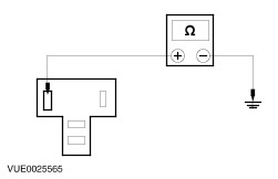
| | 1 Measure the resistance between horn relay C69 pin 5, circuit 29S-ME6 (OG/YE), harness side and ground. |
| | Is the resistance between 0.5 and 4 ohms? Yes No REPAIR circuit 29S-ME6. TEST the system for normal operation. |
| B4: CHECK POWER TO HORN SWITCH |
WARNING:To deactivate the air bag, refer to the procedure in section 501-20B for the correct air bag deactivation procedure. |
| | 1 |
| | 2 Remove the steering column lower shroud. |
| | 3 Disconnect Clockspring C896. |
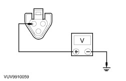
| | 4 Measure the voltage between the clockspring C896 pin 2, circuit 31S-ME7 (BK/BU), harness side and ground. |
| | Is the voltage greater than 10 volts? Yes No REPAIR circuit 31S-ME7. TEST the system for normal operation. |
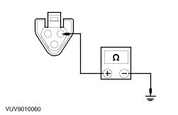
| B5: CHECK THE HORN SWITCH GROUND CIRCUIT |
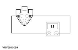
| | 1 Measure the resistance between clockspring C896 pin 1, circuit 31-ME7/PG13 (BK), harness side and ground. |
| | Is the resistance less than 5 ohms? Yes No If equipped with speed control. GO to B7. GO to Pinpoint Test B. . Otherwise, REPAIR the circuit. TEST the system for normal operation. |
| B6: CHECK THE HORN SWITCH |
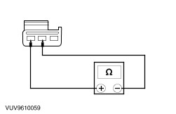
| | 1 Disconnect Horn Switch. |
| | 2 Measure the resistance between the horn switch pin B and C. Take note of the reading with the switch pressed as well as with the switch released. |
| | Is the resistance greater than 10,000 ohms with the switch released and less than 5 ohms with the switch pressed? Yes No INSTALL a new horn switch. REFER to Horn Switch in this section. TEST the system for normal operation. |
| B7: CHECK SPEED CONTROL MODULE GROUND |
| | 1 Disconnect Speed Control Module C833. |
| | 2 Measure the resistance between the speed control module C833 pin 10, circuit 91-PG12 (BK/WH), harness side and ground. |
| | Is the resistance less than 5 ohms? Yes REPAIR circuit 31-PG13. TEST the system for normal operation. No REPAIR circuit 91-PG12. TEST the system for normal operation. |