| Diagnosis and Testing Refer to Wiring Diagrams Section 417-01, for schematic and connector information. Special Tool(s) | | Set of adapter plugs for test probes 29-011A | | | Break-out box 29-001 | | | Test lead no. 5 33-003 | Inspection and Verification - Visually check the system for obvious mechanical or electrical damage.
Visual Inspection Chart | Electrical | - Fuse(s)
- Wiring harness.
- Bulb(s)
- Connector
- Switch
- Rear lamp assembly
| - Resolve any obvious causes or concerns found during the visual inspection before carrying out any further tests.
- If the concern persists, verify the symptom and continue with the symptom chart
Symptom chart Symptom chart | Symptom | Possible Sources | Action | | Both reversing lamps inoperative | * Circuit(s) or connection(s) * Transmission switch or selector lever position sensor | * GO to Pinpoint Test ??. | | Left reversing lamp inoperative | * Circuit(s) or connection(s) * Left-hand rear lamp assembly * Reversing lamp bulb. | * GO to Pinpoint Test ??. | | Right reversing lamp inoperative | * Circuit(s) or connection(s) * Right-hand rear lamp assembly. * Reversing lamp bulb. | * GO to Pinpoint Test ??. | | Reversing lamp permanently lit | * Circuit(s) or connection(s) * Transmission switch or selector lever position sensor * Main navigation unit. * Navigation component with CD-ROM player. * Instrument interface module. * Park distance control module. * Powertrain control module (PCM) | * GO to Pinpoint Test ??. | Pinpoint test | PINPOINT TEST A : BOTH REVERSING LAMPS INOPERATIVE | | TEST CONDITIONS | DETAILS/RESULTS/ACTIONS | | A1: CHECK THE GROUND CONNECTION | | | 1 Ignition switch in position II. | | | 2 Switch on the left and right turn signals respectively. | | | 3 Check the turn signal lamps. | | | Do all the turn signal lamps work? Yes No REPAIR break in circuit 31-DB1 (BK). CHECK the operation of the system | | A2: CHECK CIRCUIT 14-LG28 (OR 15-LG28) FOR OPEN CIRCUIT | | | 1 Ignition switch in position 0. | | | 2 Disconnect . 3 Transmission switch C862 (or C2066) - Selector lever position sensor C438
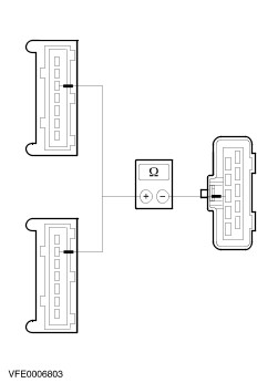
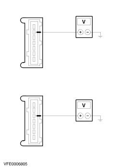
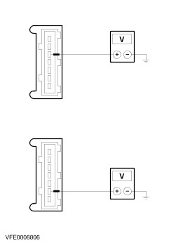
| | | 4 Ignition switch in position II. | | | 5 Measure the voltage between transmission switch C862 or C2066 (manual transmission) or selector lever position sensor C438 (automatic transmission), pin 1, circuit 14-LG28 (VT/WH) or 15-LG28 (GN/WH), wiring harness side and ground. | | | Is battery voltage displayed? Yes No REPAIR break in circuit 14-LG28 (VT/WH) or 15-LG28 (GN/WH). RETEST the system. | | A3: DETERMINE EQUIPMENT | | | 1 Determine equipment. | | | Is the vehicle equipped with an automatic transmission? Yes No | | A4: CHECK THE CIRCUIT BETWEEN THE SELECTOR LEVER POSITION SENSOR AND THE REAR LAMP ASSEMBLY/ASSEMBLIES FOR OPEN CIRCUIT | | | 1 Ignition switch in position 0. | | | 2 Disconnect Left-hand rear lamp assembly C446 or C2021. | | | 3 Measure the resistance between the selector lever position sensor, connector C438, pin 3, circuit 14S-LG9 (VT/BK) or 15S-LG9 (GN/BK), wiring harness side and the left-hand rear lamp assembly, connector C446 (or C2021 with trailer coupling), pin 5 (estate), pin 6 (4-/5-door versions), wiring harness side. | | | Is the resistance less than 5 Ohm? Yes CHECK connection C438 and RENEW the selector lever position sensor as necessary. RETEST the system. No REPAIR break in circuit 14S-LG9(A/B) (VT/BK) or 15S-LG9(A) (GN/BK). RETEST the system. | | A5: CHECK THE CIRCUIT BETWEEN THE TRANSMISSION SWITCH AND THE REAR LAMP ASSEMBLY FOR OPEN CIRCUIT | | | 1 Ignition switch in position 0. | | | 2 Disconnect Left-hand rear lamp assembly C446 or C2021. | | | 3 Measure the resistance between the transmission switch, connector C862 (or C2066), pin 2, circuit 14S-LG9 (VT/BK) or 15S-LG9 (GN/BK), wiring harness side and the left-hand rear lamp assembly, connector C446 (or C2021 with trailer coupling), pin 5 (estate), pin 6 (4-/5-door versions), circuit 14S-LG9 (VT/BK) or 15S-LG9 (GN/BK) (or (GN) or (VT/OG) with trailer coupling), wiring harness side. | | | Is the resistance less than 5 Ohm? Yes CHECK connection C862 (or C2066) and if necessary RENEW the transmission switch. RETEST the system. No REPAIR break in circuit 14S-LG9(A/B) (VT/BK) or 14S-DA2 (VT/BU) or 14S-DA3 (VT) or 15S-LG9(A) (GN/BK). RETEST the system. | | PINPOINT TEST B : LEFT REVERSING LAMP INOPERATIVE | | TEST CONDITIONS | DETAILS/RESULTS/ACTIONS | | B1: CHECK THE GROUND CONNECTION | | | 1 Ignition switch in position II. | | | 2 Switch on the left turn signal lamps. | | | 3 Check the turn signal lamp. | | | Does the turn signal lamp work? Yes Without trailer coupling: After checking the reversing lamp bulb and plug connection C2021, RENEW the left-hand rear lamp assembly. RETEST the system. No | | B2: CHECK VT/OG OR GN CIRCUIT FOR BREAKS | | | 1 Ignition switch in position 0. | | | 2 Disconnect Left-hand rear lamp assembly C2021. | | | 3 Ignition switch in position II. | | | 4 Engage reverse gear. | | | 5 Measure the voltage between the left-hand rear lamp assembly, connector C2021, pin 6 (or pin 5 on an estate), circuit (VT/OG) or (GN), wiring harness side and ground. | | | Is battery voltage displayed? Yes After checking the reversing lamp bulb and plug connection C2021, RENEW the left-hand rear lamp assembly. RETEST the system. No REPAIR break in circuit (VT/OG) or (GN). RETEST the system. | | B3: CHECK THE GROUND CONNECTION OF THE REAR LAMP ASSEMBLY | | | 1 Ignition switch in position 0. | | | 2 Disconnect Left-hand rear lamp assembly C446 or C2021. | | | 3 Measure the resistance between the left-hand rear lamp assembly, connector C446 (or C2021 on a vehicle with a trailer coupling), pin 4 (or pin 6 on an estate), circuit 31-LF11 (BK) (or (BN) on a vehicle with a trailer coupling), wiring harness side and ground. | | | Is the resistance less than 5 Ohm? Yes After checking the reversing lamp bulb and plug connection C446 or C2021, RENEW the left-hand rear lamp assembly. RETEST the system. No REPAIR the break in circuit 31-LF11 (BK) or (BN). RETEST the system. | | PINPOINT TEST C : RIGHT REVERSING LAMP INOPERATIVE | | TEST CONDITIONS | DETAILS/RESULTS/ACTIONS | | C1: CHECK THE GROUND CONNECTION | | | 1 Ignition switch in position II. | | | 2 Switch on the right-hand turn signal. | | | 3 Check the turn signal lamp. | | | Does the turn signal lamp work? Yes No | | C2: CHECK CIRCUIT 14S-LG16 (VT/OG) OR 15S-LG16 (GN/OG) OR (GN) OR (VT/OG) FOR OPEN CIRCUIT | | | 1 Ignition switch in position 0. | | | 2 Disconnect Right-hand rear lamp assembly C447 or C2017. | | | 3 Ignition switch in position II. | | | 4 Engage reverse gear. | | | 5 Measure the voltage between the right-hand rear lamp assembly, connector C447 (or connector C2017 on vehicles with a trailer coupling), pin 2 (or pin 5 on an estate), wiring harness side and ground. | | | Is battery voltage displayed? Yes After checking the reversing lamp bulb and plug connection C447 or C2017, RENEW the right-hand rear lamp assembly. RETEST the system. No REPAIR the break in circuit 14S-LG16 (VT/OG) or 15S-LG16 (GN/OG) (or (GN) or (VT/OG) on vehicles with a trailer coupling). RETEST the system. | | C3: CHECK THE GROUND CONNECTION OF THE REAR LAMP ASSEMBLY | | | 1 Ignition switch in position 0. | | | 2 Disconnect Right-hand rear lamp assembly C447 or C2017. | | | 3 Measure the resistance between the right-hand rear lamp assembly, connector C447 (or C2017 on a vehicle with a trailer coupling), pin 4 (or pin 6 on an estate), circuit 31-LF20 (BK) (or (GN) on a vehicle with a trailer coupling), wiring harness side and ground. | | | Is the resistance less than 5 Ohm? Yes After checking the reversing lamp bulb and plug connection C447 or C2017, RENEW the right-hand rear lamp assembly. RETEST the system. No REPAIR the break in circuit 31-LF20 (BK) or (BN). RETEST the system. | | PINPOINT TEST D : REVERSING LAMP PERMANENTLY LIT | | TEST CONDITIONS | DETAILS/RESULTS/ACTIONS | | D1: CHECK THE OPERATION OF THE SELECTOR LEVER POSITION SENSOR OR THE TRANSMISSION SWITCH | | | 1 Ignition switch in position 0. | | | 2 Disconnect . 3 Transmission switch C862 (or C2066) - Selector lever position sensor C438
| | | 4 Ignition switch in position II. | | | 5 Check the reversing lamps. | | | Do the reversing lamps remain permanently lit? Yes No CHECK plug connection C438 or C862 or C2066, and if necessary RENEW the transmission switch or the selector lever position sensor. RETEST the system. | | D2: CHECK CIRCUITS FOR SHORT TO B+ | NOTE:Depending on equipment levels disconnect the following modules. | NOTE:Before connecting a module switch the ignition off, then connect the module and switch the ignition back on. | | | 1 Ignition switch in position 0. | | | 2 Disconnect Park distance control module C1b. | | | 3 Disconnect PCM C68 (diesel only). | | | 4 Disconnect Instrument cluster auxiliary module C440 (RHD only, with automatic transmission).. | | | 5 Disconnect Main navigation unit C2011a. | | | 6 Disconnect Navigation component with CD-ROM player C1946. | | | 7 Ignition switch in position II. | | | 8 Check the reversing lamps. | | | Do the reversing lamps remain permanently lit? Yes LOCATE and RECTIFY short to B+ in circuits connected to soldered connection S292 (or S286 on diesel vehicles) with the aid of the Wiring Diagrams. RETEST the system. No Reconnect the modules individually in the reverse order. After connecting each module check whether the reversing lamps are permanently lit up. As soon as the reversing lamps light up CHECK the last module that was reconnected and RENEW it as necessary. RETEST the system. | |