| Diagnosis and Testing Inspection and Verification - Verify the customer concern.
- Visually inspect for obvious signs of mechanical or electrical damage.
- If an obvious cause for an observed or reported concern is found, correct the cause (if possible) before proceeding to the next step.
- If the concern is not visually evident, verify the symptom and refer to the Symptom Chart.
Visual Inspection Chart | Mechanical | Electrical | | | - Fuse(s).
- Wiring harness.
- Loose or corroded connector(s).
- Motor(s).
- Switch(es).
- Electrical connector(s).
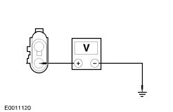
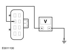
| Symptom Chart Symptom Chart | Symptom | Possible Sources | Action | | The power seat is inoperative | * Seat control switch. | * CARRY OUT the Seat Control Switch Component Test. REFER to the Wiring Diagrams. | | * Circuit(s). | * GO to Pinpoint Test ??. | | The power seat moves but is noisy | * Seat base assembly. * Motor(s). | * GO to Pinpoint Test ??. | | The power seat moves but is loose | * Seat tracks(s). * Seat base assembly. | * GO to Pinpoint Test ??. | | The power seat does not make full travel | * Fastening hardware. * Seat base assembly. | * GO to Pinpoint Test ??. | | The power seat does not move horizontally/vertically | * Motor. * Circuit(s). | * GO to Pinpoint Test ??. | | The power seat does not recline | * Seat control switch. | * CARRY OUT the Seat Control Switch Component Test. REFER to the Wiring Diagrams. | | * Motor. * Circuit(s). | * GO to Pinpoint Test ??. | | The power lumbar is inoperative | * Seat control switch. | * CARRY OUT the Seat Control Switch Component Test. REFER to the Wiring Diagrams. | | * Motor. * Circuit(s). | * GO to Pinpoint Test ??. | | The heated seat is inoperative | * Heated seat control switch(es). | * CARRY OUT the Heated Seat Control Switch Component Test. REFER to the wiring Diagrams. | | * Circuit(s). * Heater mat(s). | * GO to Pinpoint Test ??. | | The heated seats are inoperative | * Heated seat control switch(es). | * CARRY OUT the Heated Seat Control Switch Component Test. REFER to the wiring Diagrams. | | * Circuit(s). * Heated seat relay. | * GO to Pinpoint Test ??. | Pinpoint Tests | PINPOINT TEST A : THE POWER SEAT IS INOPERATIVE | | TEST CONDITIONS | DETAILS/RESULTS/ACTIONS | | A1: CHECK THE VOLTAGE SUPPLY TO THE POWER SEAT SWITCH | | | 1 Ignition switch in position 0. | | | 2 Disconnect Power seat control switch. | | | 3 Ignition switch in position II. | | | 4 Measure the voltage between the power seat switch C1852a pin 2, circuit 29-AH6 (OG/YE), 10-way power seat (C715 pin 2, circuit 29-AH6 [OG/YE], 2-way power seat) harness side and ground. | | | Is the voltage greater than 10 volts? Yes No REPAIR circuit 29-AH6 (OG/YE). TEST the system for normal operation. | | A2: CHECK THE GROUND CIRCUIT FOR CONTINUITY | | | 1 Ignition switch in position 0. | | | 2 Measure the resistance between the power seat switch C1852a pin 1, circuit 31-AH6 (BK), 10-way power seat (C715 pin 3, circuit 31-AH6 [BK]; and pin 6, circuit 31-AH6A [BK], 2-way power seat) harness side and ground. | | | Is the resistance less than 5 ohms? Yes VERIFY the customer concern. No REPAIR circuit 31-AH6 (BK) or circuit 31-AH6A (BK). TEST the system for normal operation. | | PINPOINT TEST B : POWER SEAT MOVES BUT IS NOISY | | TEST CONDITIONS | DETAILS/RESULTS/ACTIONS | | B1: CHECK THE SEAT TRACK | | | 1 Ignition switch in position 0. | | | 2 Check the seat alignment of the track to the floor and the track to the seat. | | | Is the track out of alignment? Yes ALIGN the track to the seat and the floor. TEST the system for normal operation. No INSTALL a new seat track assembly. TEST the system for normal operation. | | PINPOINT TEST C : THE POWER SEAT MOVES BUT IS LOOSE | | TEST CONDITIONS | DETAILS/RESULTS/ACTIONS | | C1: CHECK THE FASTENING HARDWARE | | | 1 CHECK the hardware fastening the seat | | | Is the fastening hardware loose? Yes CHECK and tighten the fastening hardware to specifications. For additional information, refer to the procedure in this section. No INSTALL a new seat base assembly. TEST the system for normal operation. | | PINPOINT TEST D : THE POWER SEAT DOES NOT MAKE FULL TRAVEL | | TEST CONDITIONS | DETAILS/RESULTS/ACTIONS | | D1: CHECK THE SEAT BASE FOR OBSTRUCTIONS | | | 1 Remove the seat. | | | Are there any obstructions fouling the seat base assembly? Yes REMOVE the obstruction(s). LUBRICATE the seat base mechanism. TEST the seat for normal operation. No | | D2: CHECK THE SEAT BASE FOR MECHANICAL DAMAGE | NOTE:The seat base is serviced as an assembly. It is not possible to realign the tracks in service. | | | 1 CHECK the seat base: - Drive cables for damage/connection
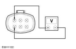
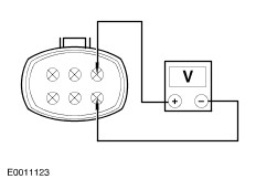
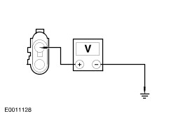
| | | Is there any damage or detachment of drive cables? Yes REPAIR the damaged components (if possible). INSTALL a new seat height motor. INSTALL a new seat base mechanism. TEST the seat for normal operation. No INSTALL a new seat base assembly. TEST the seat for normal operation. | | PINPOINT TEST E : THE POWER SEAT DOES NOT MOVE HORIZONTALLY/VERTICALLY | | TEST CONDITIONS | DETAILS/RESULTS/ACTIONS | | E1: CHECK THE POWER SEAT SWITCH | | | 1 CHECK the power seat control switch. For additional information, refer to the Wiring Diagrams Section 700-09. | | | Is the switch OK? Yes If the seat does not move horizontally GO to E2. . If the 10-way seat does not move vertically at the front GO to E3. . If the 10-way seat does move vertically at the rear GO to E4. . If the 2-way seat does not move vertically GO to E5. . No INSTALL a new power seat control switch. TEST the system for normal operation. | | E2: CHECK THE VOLTAGE SUPPLY TO THE FORWARD/REARWARD MOTOR | | | 1 Ignition switch in position 0. | | | 2 Disconnect Power seat control switch C1852d. | | | 3 Ignition switch in position II. | | | 4 Operate the power seat control switch. | | | 5 Measure the voltage between the power seat switch C1852d pin 1, circuit 33-AH9 (YE/GN) and pin 4, circuit 32-AH9 (WH/GN) | | | Is the voltage greater than 10 volts and is the polarity reversed when the switch is operated between the FORWARD and REARWARD position? Yes INSTALL a new forward/rearward motor. TEST the system for normal operation. No VERIFY the customer concern. | | E3: CHECK THE VOLTAGE SUPPLY TO THE FRONT HEIGHT MOTOR | | | 1 Operate the power seat control switch. | | | 2 Measure the voltage between the power seat switch C1852d pin 3, circuit 33-AH10 (YE/BK) and pin 6, circuit 32-AH10 (WH/BK). | | | Is the voltage greater than 10 volts and is the polarity reversed when the switch is operated between the UP and the DOWN position? Yes INSTALL a new front height motor. TEST the system for normal operation. No VERIFY the customer concern. | | E4: CHECK THE VOLTAGE SUPPLY TO THE REAR HEIGHT MOTOR | | | 1 Operate the power seat control switch. | | | 2 Measure the voltage between the power seat switch C1852d pin 2, circuit 33-AH11 (YE/VT) and pin 5, circuit 32-AH11 (WH/VT). | | | Is the voltage greater than 10 volts and is the polarity reversed when the switch is operated between the UP position and the DOWN position? Yes INSTALL a new rear height motor. TEST the system for normal operation. No VERIFY the power seat switch condition. TEST the system for normal operation. | | E5: CHECK THE VOLTAGE SUPPLY TO THE HEIGHT MOTOR | | | 1 Operate the power seat control switch. | | | 2 Measure the voltage between the height motor C2034 pin 1, circuit 32-AH10 (WH/BK) and pin 2, circuit 33-AH10 (YE/BK) | | | Is the voltage greater then 10 volts and is the polarity reversed when the switch is operated between the UP position and the DOWN position? Yes INSTALL a new height motor. TEST the system for normal operation. No VERIFY the power seat switch condition. TEST the system for normal operation. | | PINPOINT TEST F : THE POWER SEAT DOES NOT RECLINE | | TEST CONDITIONS | DETAILS/RESULTS/ACTIONS | | F1: CHECK THE VOLTAGE SUPPLY TO THE BACKREST MOTOR | | | 1 Ignition switch in position 0. | | | 2 Disconnect Backrest motor C1852b. | | | 3 Ignition switch in position II. | | | 4 Operate the power seat control switch. | | | 5 Measure the voltage between the backrest motor C1852b pin 2, circuit 33-AH7 (YE/RD) and pin 1, circuit 32-AH7 (WH/RD). | | | Is the voltage greater than 10 volts and is the polarity reversed when the switch is operated between the FORWARD position and REARWARD position? Yes INSTALL a new backrest motor. TEST the system for normal operation. No VERIFY the customer concern. | | PINPOINT TEST G : THE POWER LUMBAR IS INOPERATIVE | | TEST CONDITIONS | DETAILS/RESULTS/ACTIONS | | G1: CHECK THE VOLTAGE SUPPLY TO THE LUMBAR COMPRESSOR MOTOR | | | 1 Ignition switch in position 0. | | | 2 Disconnect Power seat control switch C1852c. | | | 3 Ignition switch in position II. | | | 4 Operate the power seat control switch. | | | 5 Measure the voltage between the power seat switch C1852C pin 2, circuit 33-AH22 (YE/BU) and pin 1, circuit 32-AH22 (WH/BU) | | | Is the voltage greater than 10 volts and is the polarity reversed when the switch is operated between the INFLATE position and the DEFLATE position? Yes INSTALL a new lumbar compressor motor. TEST the system for normal operation. No VERIFY the customer concern. | | PINPOINT TEST H : THE HEATED SEAT IS INOPERATIVE | | TEST CONDITIONS | DETAILS/RESULTS/ACTIONS | | H1: CHECK THE OPERATION OF THE INOPERATIVE HEATED SEAT. | | | 1 Ignition switch in position II. | | | 2 Operate the inoperative seat heater switch. | | | Does the heated seat switch LED illuminate? Yes No | | H2: CHECK THE VOLTAGE SUPPLY TO THE INOPERATIVE HEATED SEAT. | | | 1 Ignition switch in position 0. | | | 2 Disconnect Cushion heater mat. | | | 3 Ignition switch in position II. | | | 4 Measure the voltage between the inoperative seat cushion heater: - C1778 pin 1, circuit 74S-HC8 (BU/WH) harness side and ground. Right-hand seat.
- C649 pin 1, circuit 74S-HC8 (BU/WH) harness side and ground. Left-hand seat.
| | | Is the voltage greater than 10 volts? Yes No REPAIR circuit 74S-HC8 (BU/WH). TEST the system for normal operation. | | H3: CHECK THE INOPERATIVE SEAT BACKREST HEATER CIRCUIT FOR CONTINUITY | | | 1 Ignition switch in position 0. | | | 2 Measure the resistance between the inoperative seat cushion heater: - C1778 pin 2, circuit 31S-HC7 (BK/BU) harness side and ground. Right-hand seat.
- C649 pin 2, circuit 31S-HC7 (BK/BU) harness side and ground. Left-hand seat.
| | | Is the resistance less than 9 ohms (resistance of the heater mat)? Yes INSTALL a new seat cushion heater. TEST the system for normal operation. No | | H4: CHECK THE INOPERATIVE SEAT BACKREST HEATER CIRCUIT FOR CONTINUITY | | | 1 Measure the resistance between the inoperative seat backrest heater: - C747 pin 1, circuit 31S-HC7 (BK/BU) backrest heater side and ground. Right-hand seat.
- C1851 pin 1, circuit 31S-HC7 (BK/BU) backrest heater side and ground. Left-hand seat.
| | | Is the resistance less than 9 ohms (resistance of the heater mat)? Yes REPAIR circuit 31S-HC7 (BK/BU). TEST the system for normal operation. No | | H5: CHECK THE INOPERATIVE HEATED SEAT SWITCH | | | 1 Ignition switch in position 0. | | | 2 Disconnect Inoperative heated seat control switch. | | | 3 Ignition switch in position II. | | | 4 Measure the voltage between the heated seat control switch: - C694 pin 2, circuit 75-HC9 (BU/BK) harness side and ground. Right-hand seat.
- C90 pin 2, circuit 75-HC6 (BU) harness side and ground. Left-hand seat.
| | | Is the voltage greater than 10 volts? Yes INSTALL a new heated seat control switch. TEST the system for normal operation. No REPAIR circuit 75-HC9 (BU/BK) or circuit 75-HC6 (BU). TEST the system for normal operation. | | H6: CHECK THE INOPERATIVE HEATED SEAT GROUND CIRCUIT | | | 1 Measure the resistance between the inoperative seat backrest heater: - C747 pin 2, circuit 31-HC7 (BK) harness side and ground. Right-hand seat.
- C1851 pin 2, circuit 31-HC7 (BK) harness side and ground. Left-hand seat.
| | | Is the resistance less than 5 ohms? Yes INSTALL a new seat backrest heater mat. TEST the system for normal operation. No REPAIR circuit 31-HC7 (BK). TEST the system for normal operation. | | PINPOINT TEST I : THE HEATED SEATS ARE INOPERATIVE | | TEST CONDITIONS | DETAILS/RESULTS/ACTIONS | | I1: CHECK THE OPERATION OF THE HEATED SEAT RELAY | | | 1 Ignition switch in position II. | | | 2 Operate the left-hand heated seat control switch. | | | Does the relay click? Yes No | | I2: CHECK THE SUPPLY VOLTAGE TO THE HEATED SEAT SWITCHES | NOTE:The circuit numbers and wiring colors change at soldered joint S9 | | | 1 Ignition switch in position 0. | | | 2 Disconnect Heated seat control switch. | | | 3 Ignition switch in position II. | | | 4 Measure the voltage between the left-hand heated seat control switch C90 pin 2, circuit 75-HC6 (BU) harness side and ground. | | | Is the voltage greater than 10 volts? Yes VERIFY the customer concern. TEST the system for normal operation. No REPAIR circuit 75-HC1 (BU/RD). TEST the system for normal operation. | | I3: CHECK THE HEATED SEAT RELAY | | | 1 Ignition switch in position 0. | | | 2 Disconnect Heated seat relay C436. | | | 3 Measure the resistance between the heated seat relay C436 pin 4, circuit 31-HC12 (BK) harness side and ground. | | | Is the resistance less than 5 ohms? Yes No REPAIR circuit 31-HC12 (BK). TEST the system for normal operation. | | I4: CHECK THE HEATED SEAT RELAY | | | 1 Ignition switch in position II. | | | 2 Measure the voltage between the heated seat relay C436 pin 1, circuit 75-HC12 (YE/RD) harness side and ground. | | | Is the voltage greater than 10 volts? Yes INSTALL a new heated seat relay. TEST the system for normal operation. No REPAIR circuit 75-HC12 (YE/RD). TEST the system for normal operation. | |