| Removal and Installation Special Tool(s) | | Installer, Halfshaft 204-161 (14-041) | | | Alignment Pins, Subframe 205-316 (15-097A) | | | Remover, Halfshaft 308-256 (16-089) | General Equipment Three leg puller Transmission jack Removal All vehicles | | -
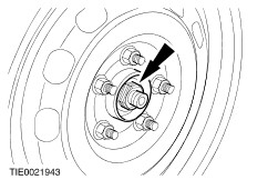
CAUTION:Use a socket to loosen the wheel hub retaining nut to prevent damage. Loosen the wheel hub retaining nut. | | | -
Detach the steering column shaft from the steering column flexible coupling. - Remove the retaining bolt.
- Rotate the clamp plate.
| | | -
Remove the suspension strut and spring assembly top mount brace cover. | | | -
Loosen the strut and spring assembly top mount retaining nuts by four turns. | | | -
Using cable ties, support the radiator on both sides. | | | -
Remove the wheel and tire.
For additional information, refer to: Wheel and Tire (204-04 Wheels and Tires, Removal and Installation).
| | | -
CAUTION:The wheel hub retaining nut can be reused four times, mark the retaining nut. Remove the wheel hub retaining nut. | Vehicles with diesel engine | | -
Remove the engine undershield. | All vehicles | | -
Remove the splash shield. | | | -
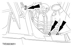
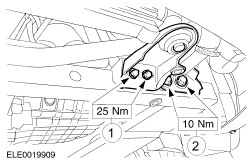
Remove the radiator support brackets. - Remove the hose bracket.
- Remove both radiator support brackets.
| Vehicles with diesel engine | | -
Detach the air intake hose. | | | -
Detach the turbocharger outlet hose. | All vehicles | | -
Detach the stabilizer bar connecting link from the suspension strut. | Vehicles with 1.8L, 2.0L or diesel engine | | -
Remove the exhaust flexible pipe.
For additional information, refer to: Exhaust Flexible Pipe (309-00 Exhaust System, Removal and Installation).
| Vehicles with 2.5L or 3.0L engine | | -
Remove the exhaust dual converter y-pipe.
For additional information, refer to: Dual Catalytic Converter Y-Pipe (309-00 Exhaust System, Removal and Installation).
| All vehicles | | -
Remove the engine rear support insulator. | All except vehicles with diesel engine | | -
Disconnect the catalyst monitor sensor electrical connector. | | | -
Detach the catalyst monitor sensor wiring harness from the subframe. | Vehicles with high intensity discharge headlamps | | -
Detach the headlamp leveling sensor wiring harness from the subframe. | All vehicles | | -
Detach the radiator cooling fan wiring harness from the subframe. | | | -
Using two suitable wooden blocks and a suitable transmission jack, support the subframe. | | | -
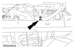
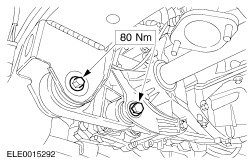
CAUTION:Do not pull down the lower arm, to prevent the lower arm hydro-bushing from damage. Remove the lower arm ball joint retaining nut and bolt. | | | -
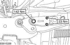
Remove the subframe rear retaining bolts and the subframe bracket retaining bolts on both sides. | | | -
Remove the subframe front retaining bolts on both sides. | | | -
CAUTION:Lower the subframe uniformly, to prevent the lower arm hydro-bushing from damage. | | | -
CAUTION:Protect the ball joint seal using a soft cloth to prevent damage. Detach the lower arm ball joint from the wheel knuckle. | | | -
CAUTION:Support the halfshaft. The inner joint must not be bent more than 18 degrees. The outer joint must not be bent more than 45 degrees. CAUTION:Do not damage the halfshaft seal. NOTE:Plug the transaxle to prevent fluid loss or dirt ingress. Using the special tool, detach the halfshaft from the transaxle and secure it to one side. - Allow the fluid to drain into a suitable container.
- Remove and discard the snap ring.
| | | -
Using a suitable three leg puller, detach the halfshaft from the wheel hub and remove the halfshaft. | Installation All vehicles | | -
CAUTION:Support the halfshaft. The inner joint must not be bent more than 18 degrees. The outer joint must not be bent more than 45 degrees. CAUTION:Do not damage the halfshaft seal. CAUTION:Make sure the snap ring is correctly seated. NOTE:Install a new snap ring. Attach the left-hand halfshaft to the transaxle. | | | -
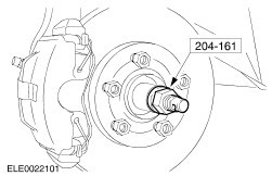
CAUTION:Make sure the halfshaft is completely installed into the wheel hub. Using the special tool, install the halfshaft. | | | -
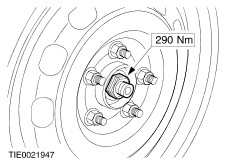
CAUTION:The wheel hub retaining nut can be reused four times, inspect the markings on the retaining nut and install a new retaining nut if necessary. NOTE:Do not fully tighten the retaining nut at this stage. Install the wheel hub retaining nut. | | | -
CAUTION:Make sure the heat shield is installed to prevent damage to the ball joint. Attach the lower arm to the wheel knuckle on both sides. | | | -
Using the special tool and a suitable washer, align the subframe. - Insert the washer with inside diameter 22 mm, outside diameter 44 mm and height 5 mm, into the subframe above the lower alignment hole.
- Insert the alignment pin through the subframe alignment holes and the washer.
- Slide the locking plates on top of the washer and into the groove of the tool and tighten the alignment pin sleeve.
| | | -
CAUTION:While tightening the subframe retaining bolts, make sure the subframe does not move. Install the subframe rear retaining bolts and the subframe bracket retaining bolts on both sides. | | | -
CAUTION:While tightening the subframe retaining bolts, make sure the subframe does not move. Install the subframe front retaining bolts. | | | -
Remove the special tools. | | | -
WARNING:Install a new self-locking nut. Install the lower arm joint pinch bolt from the rear, the retaining nut from the front. | | | -
Attach the radiator cooling fan wiring harness to the subframe. | Vehicles with high intensity discharge headlamps | | -
Attach the headlamp leveling sensor wiring harness to the subframe. | All except vehicles with diesel engine | | -
Attach the catalyst monitor sensor wiring harness to the subframe. | | | -
Connect the catalyst monitor sensor electrical connector. | All vehicles | | -
Install the engine rear support insulator. | Vehicles with 1.8L, 2.0L or diesel engine | | -
Install the exhaust flexible pipe.
For additional information, refer to: Exhaust Flexible Pipe (309-00 Exhaust System, Removal and Installation).
| Vehicles with 2.5L or 3.0L engine | | -
Install the exhaust dual converter y-pipe.
For additional information, refer to: Dual Catalytic Converter Y-Pipe (309-00 Exhaust System, Removal and Installation).
| All vehicles | | -
Attach the stabilizer bar connecting link to the suspension strut. | Vehicles with diesel engine | | -
Attach the turbocharger outlet hose. | | | -
Attach the air intake hose. | All vehicles | | -
Install the radiator support brackets. - Install both radiator supports brackets.
- Install the hose brackets.
| | | -
Install the splash shield. | Vehicles with diesel engine | | -
Install the engine undershield. | All vehicles | | -
Install the front wheel and tire.
For additional information, refer to: Wheel and Tire (204-04 Wheels and Tires, Removal and Installation).
| | | -
Tighten the wheel hub retaining nut. | | | -
Tighten the strut and spring assembly top mount retaining nuts. | | | -
Install the suspension strut and spring assembly top mount brace cover. | | | -
WARNING:Install a new steering column to steering column flexible coupling retaining bolt. Failure to follow this instruction may result in personal injury. Connect the steering column shaft to the steering column flexible coupling. - Rotate the clamp plate.
- Install the retaining bolt.
| Vehicles with 4-speed automatic transaxle | | -
Refill the automatic transaxle.
For additional information, refer to: Transmission Fluid Drain and Refill (307-01A Automatic Transmission/Transaxle - Vehicles With: 4-Speed Automatic Transmission (CD4E), General Procedures).
| Vehicles with 5-speed automatic transaxle | | -
Check the automatic transaxle fluid level and top up with automatic transmission fluid, if necessary.
For additional information, refer to: Transmission Fluid Level Check (307-01B Automatic Transmission/Transaxle - Vehicles With: 5-Speed Automatic Transmission (5F31J), General Procedures).
| Vehicles with 5-speed manual transaxle (MTX-75) | | -
Check the transmission fluid level and top up with manual transmission fluid, if necessary.
For additional information, refer to: Fill Procedure (308-03A Manual Transmission/Transaxle - Vehicles With: 5-Speed Manual Transmission (MTX-75), General Procedures).
| Vehicles with 6-speed manual transaxle | | -
Check the transmission fluid level and top up with manual transmission fluid, if necessary.
For additional information, refer to: Fill Procedure (308-03B Manual Transmission/Transaxle - Vehicles With: 6-Speed Manual Transmission (MMT6), General Procedures).
| |