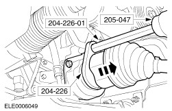
| Removal and Installation Special Tool(s) | | Remover, Halfshaft 204-226 (16-092) | | | Adapter for 204-226 204-226-01 (16-092-01) | | | Slide hammer 205-047 (15-011) | Removal All vehicles | | -
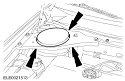
Remove the right-hand suspension strut and spring assembly top mount brace cover. | | | -
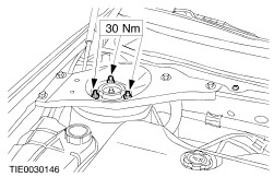
Loosen the strut and spring assembly top mount retaining nuts by four turns. | | | -
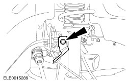
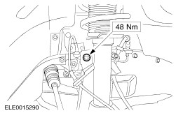
Detach the right-hand stabilizer connecting link from the suspension strut and spring assembly. | | | -
Remove the right-hand wheel and tire.
For additional information, refer to: Wheel and Tire (204-04 Wheels and Tires, Removal and Installation).
| | | -
NOTE:The lower arm remains installed. Detach the right-hand lower arm ball joint from the wheel knuckle.
For additional information, refer to: Lower Arm (204-01 Front Suspension, Removal and Installation).
| | | -
CAUTION:Support the halfshaft. The inner joint must not be bent more than 18 degrees. The outer joint must not be bent at more than 45 degrees. Using the special tools, detach the right-hand halfshaft from the intermediate shaft and secure it to one side (vehicles with 2.5L engine shown). - Remove and discard the snap ring.
| Vehicles with 2.5L or 3.0L engine | | -
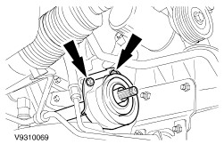
CAUTION:Do not damage the halfshaft seal. NOTE:Plug the transaxle to prevent fluid loss and dirt ingress. Remove the intermediate shaft. - Remove and discard the center bearing locknuts.
- Allow the fluid to drain into a suitable container.
| Vehicles with diesel engine | | -
CAUTION:Do not damage the halfshaft seal. NOTE:Plug the transaxle to prevent fluid loss or dirt ingress. Remove the intermediate shaft. - Remove and discard the center bearing cap and locknuts.
- Allow the fluid to drain into a suitable container.
| Vehicles with 1.8L or 2.0L engine | | -
CAUTION:Do not damage the halfshaft seal. NOTE:Plug the transaxle to prevent fluid loss or dirt ingress. Remove the intermediate shaft. - Remove and discard the center bearing cap and locknuts.
- Allow the fluid to drain into a suitable container.
| Installation All Vehicles | | -
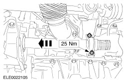
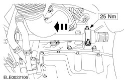
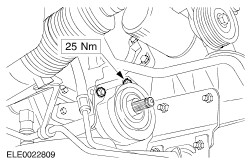
CAUTION:Do not damage the halfshaft seal. NOTE:Install a new halfshaft center bearing cap and locknuts. Install the intermediate shaft. - Install the center bearing cap.
| Vehicles with diesel engine | | -
CAUTION:Do not damage the damage the halfshaft seal. NOTE:Install a new halfshaft center bearing cap and locknuts. Install the intermediate shaft. - Install the center bearing cap.
| Vehicles with 2.5L or 3.0L engine | | -
CAUTION:Do not damage the halfshaft seal. NOTE:Install new halfshaft center bearing locknuts. Install the intermediate shaft. | All vehicles | | -
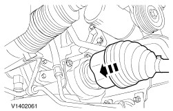
CAUTION:Support the halfshaft. The inner joint must not be bent more than 18 degrees. The outer joint must not be bent at more than 45 degrees. CAUTION:Make sure the snap ring is correctly seated. NOTE:Install a new snap ring. Attach the right-hand halfshaft to the intermediate shaft (vehicles with 2.5L engine shown). | | | -
Attach the right-hand lower arm ball joint to the wheel knuckle.
For additional information, refer to: Lower Arm (204-01 Front Suspension, Removal and Installation).
| | | -
Attach the right-hand stabiliser connecting link to the suspension strut. | | | -
Install the right-hand wheel and tire.
For additional information, refer to: Wheel and Tire (204-04 Wheels and Tires, Removal and Installation).
| | | -
Tighten the strut and spring assembly top mount retaining nuts. | | | -
Install the right-hand suspension strut and spring assembly top mount brace cover. | Vehicles with 4-speed automatic transaxle | | -
Refill the automatic transaxle.
For additional information, refer to: Transmission Fluid Drain and Refill (307-01A Automatic Transmission/Transaxle - Vehicles With: 4-Speed Automatic Transmission (CD4E), General Procedures).
| Vehicles with 5-speed automatic transaxle | | -
Check the automatic transaxle fluid level and top up with automatic transmission fluid, if necessary.
For additional information, refer to: Transmission Fluid Level Check (307-01B Automatic Transmission/Transaxle - Vehicles With: 5-Speed Automatic Transmission (5F31J), General Procedures).
| Vehicles with 5-speed manual transaxle (MTX-75) | | -
Check the transmission fluid level and top up with manual transmission fluid, if necessary.
For additional information, refer to: Fill Procedure (308-03A Manual Transmission/Transaxle - Vehicles With: 5-Speed Manual Transmission (MTX-75), General Procedures).
| Vehicles with 6-speed manual transaxle | | -
Check the transmission fluid level and top up with manual transmission fluid, if necessary.
For additional information, refer to: Fill Procedure (308-03B Manual Transmission/Transaxle - Vehicles With: 6-Speed Manual Transmission (MMT6), General Procedures).
| |