| Diagnosis and Testing Refer to Wiring Diagrams Section 310-03, for schematic and connector information. Principles of Operation There are two basic types of speed control: - Mechanical speed control
- Electronic speed control
MECHANICAL SPEED CONTROL The mechanical speed control system consists of one main component, the speed control actuator. Vehicles with a cable operated throttle body are equipped with this type of speed control system. The speed control actuator receives speed control commands from the steering wheel mounted speed control switches. The vehicle speed is monitored by the speed control actuator using the signal from the vehicle speed sensor (VSS). The vehicle speed is adjusted by means of a cable fitted to a cam, driven by a proportional electric motor housed in the speed control actuator. This cable is connected to the throttle body and operates the throttle linkage in the same way as a traditional accelerator cable. To prevent the vehicle engine working against the vehicle braking system, the brake pedal position (BPP) switch is used to monitor brake pedal movement. If the BPP switch is actuated, the speed control will disengage and normal engine operation will resume. To prevent uncontrolled engine acceleration with no transmission load, the clutch pedal position (CPP) switch is used to monitor clutch pedal movement. If the CPP switch is actuated, the speed control will disengage. The speed control system will not be enabled until the vehicles indicated road speed is 42 km/h (26.3 mph) or above. At this speed, the operation of the speed control ON switch will put the speed control system into standby mode. The instrument cluster speed control indicator lamp will not be illuminated. Standby mode will be maintained until the speed control OFF switch has been operated or the ignition key has been turned to position 0. Standby mode will be maintained if the vehicle indicated speed decreases below 42 km/h (26.3 mph). Speed control cruise function is disabled until the following criteria is met: - The vehicle indicated speed is above 42 km/h (26.3 mph)
- The speed control + switch is pressed
As long as these criteria are met, the instrument cluster speed control indicator lamp will illuminate to indicate the vehicle is under speed control. ELECTRONIC SPEED CONTROL The electronic speed control is restricted to vehicles with no accelerator cable. This type of speed control uses the PCM engine and transmission inputs and outputs to monitor, adjust and maintain the required vehicle speed. The PCM receives speed control commands from the steering wheel mounted speed control switches. Vehicle speed is monitored from the VSS input to the instrument cluster speedometer. Speed control is achieved by the direct input command from the PCM to the throttle body motor. The speed control system will not be enabled until the vehicles indicated road speed is 42 km/h (26.3 mph) or above. At this speed, the operation of the speed control ON switch will put the speed control system into standby mode. The instrument cluster speed control indicator lamp will not be illuminated. Standby mode will be maintained until the speed control OFF switch has been operated or the ignition key has been turned to position 0. Standby mode will be maintained if the vehicle indicated speed decreases below 42 km/h (26.3 mph). Speed control cruise function is disabled until the following criteria is met: - The vehicle indicated speed is above 42 km/h (26.3 mph)
- For vehicles with manual transaxle, third gear or above must been selected
- For vehicles with automatic transaxle, drive (D) must be selected
- The speed control + switch is pressed
As long as these criteria are met, the instrument cluster speed control indicator lamp will illuminate, indicating the vehicle is under speed control. To prevent the vehicle engine working against the vehicle braking system, the BPP switch is used to monitor brake pedal movement. If the BPP switch is actuated, the speed control will disengage and normal engine operation will resume. To prevent uncontrolled engine acceleration with no transmission load, the CPP switch is used to monitor clutch pedal movement. If the CPP switch is actuated, the speed control will disengage. Inspection and Verification - Verify the customer concern.
- Visually inspect for obvious signs of electrical or mechanical damage.
Visual Inspection Chart | Mechanical | Electrical | - Speed control actuator cable.
| - Fuse(s)
- Wiring harness
- Electrical connector(s)
- Speed control switch(es)
- Speed control actuator (if equipped)
- PCM
- BPP switch
- CPP switch
| - If an obvious cause for an observed or reported concern is found, correct the cause (if possible) before proceeding to the next step.
- If the cause is not visually evident verify the symptom and refer to the Symptom Chart.
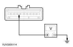
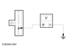
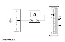
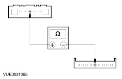
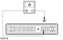
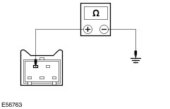
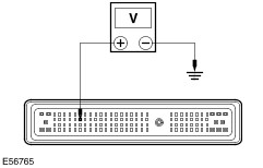
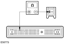
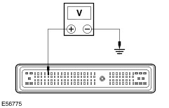
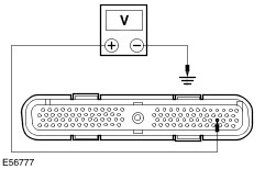
Symptom Chart | Symptom | Possible Sources | Action | | The speed control is inoperative | * Fuse(s). * Circuit(s). * Speed control actuator. * Steering wheel/speed control switch. * PCM. * BPP switch. * CPP switch. | * Vehicles with 1.8L Duratec-HE/2.0L Duratec-HE/2.5L Duratec-VE/3.0L Duratec-SE/3.0L Duratec-ST engine, GO to Pinpoint Test A. * Vehicles with 1.8L Duratec-SCi engine, GO to Pinpoint Test D. * Vehicles with 2.0L Duratorq-TDCi/2.2L Duratorq-TDCi engine, with intergrated injector driver module (IDM), GO to Pinpoint Test G. * Vehicles with 2.0L Duratorq-TDCi engine, with separate IDM, GO to Pinpoint Test J. | | The speed control does not disengage when the brakes are applied. | * Circuit(s). * BPP switch. * Speed control actuator. * PCM. | * Vehicles with 1.8L Duratec-HE/2.0L Duratec-HE/2.5L Duratec-VE/3.0L Duratec-SE/3.0L Duratec-ST engine, GO to Pinpoint Test B. * Vehicles with 1.8L Duratec-SCi engine, GO to Pinpoint Test E. * Vehicles with 2.0L Duratorq-TDCi/2.2L Duratorq-TDCi engine, with intergrated injector driver module (IDM), GO to Pinpoint Test H. * Vehicles with 2.0L Duratorq-TDCi engine, with seperate IDM, GO to Pinpoint Test K. | | The speed control does not disengage when the clutch is applied. | * Circuit(s). * CPP switch. * Speed control actuator. * PCM. | * Vehicles with 1.8L Duratec-HE/2.0L Duratec-HE/2.5L Duratec-VE/3.0L Duratec-SE/3.0L Duratec-ST engine, GO to Pinpoint Test C. * Vehicles with 1.8L Duratec-SCi engine, GO to Pinpoint Test F. * Vehicles with 2.0L Duratorq-TDCi/2.2L Duratorq-TDCi engine, with intergrated injector driver module (IDM), GO to Pinpoint Test I. * Vehicles with 2.0L Duratorq-TDCi engine, with seperate IDM, GO to Pinpoint Test L. | | The speed control switch does not operate correctly | * Steering wheel/speed control switch. | * CARRY OUT the speed control switch component test in this section. | Pinpoint Test NOTE:Use a digital multimeter for all electrical measurements. | PINPOINT TEST A : THE SPEED CONTROL IS INOPERATIVE - VEHICLES WITH 1.8L DURATEC-HE/2.0L DURATEC-HE/2.5L DURATEC-VE/3.0L DURATEC-SE/3.0L DURATEC-ST ENGINE | | TEST CONDITIONS | DETAILS/RESULTS/ACTIONS | | A1: CHECK CIRCUIT 15-PG12 (GN/WH) FOR VOLTAGE | | | 1 Disconnect Speed Control Actuator C175. | | | 2 Ignition switch in position II. | | | 3 Measure the voltage between the speed control actuator C175 pin 7, circuit 15-PG12 (GN/WH), harness side and ground. | | | Is the voltage greater than 10 volts? Yes No REPAIR the circuit. TEST the system for normal operation. | | A2: CHECK CIRCUIT 31-PG12 (BK) TO GROUND | | | 1 Ignition switch in position 0. | | | 2 Measure the resistance between the speed control actuator C175 pin 10, circuit 31-PG12 (BK), harness side and ground. | | | Is the resistance less than 5 ohms? Yes No REPAIR the circuit. TEST the system for normal operation. | | A3: CHECK CIRCUIT 8-PG13 (WH) FOR VOLTAGE | | | 1 Ignition switch in position II. | | | 2 Measure the voltage between the speed control actuator C175 pin 5, circuit 8-PG13 (WH), harness side and ground. | | | With the speed control ON switch pressed, is the voltage greater than 10 volts? Yes No | | A4: CHECK CIRCUIT 15-PG13 (GN/YE) FOR VOLTAGE | WARNING:To deactivate the air bag module, refer to the procedure in Section 501-20B for the correct air bag module deactivation procedure. Failure to follow this instruction may result in personal injury. | | | 1 Remove the driver air bag module,
REFER to: Driver Air Bag Module (501-20B Supplemental Restraint System, Removal and Installation).
| | | 2 Disconnect Clockspring C413. | | | 3 Connect the battery ground cable. | | | 4 Ignition switch in position II. | | | 5 Measure the voltage between the clockspring C413 pin 7, circuit 15-PG13 (GN/YE), harness side and ground. | | | Is the voltage greater than 10 volts? Yes No REPAIR the circuit. TEST the system for normal operation. | | A5: CHECK CIRCUIT 8-PG13 (WH) FOR OPEN CIRCUIT | | | 1 Ignition switch in position 0. | | | 2 Measure the resistance between the clockspring C413 pin 5, circuit 8-PG13 (WH), harness side and the speed control actuator C175 pin 5, circuit 8-PG13 (WH), harness side. | | | Is the resistance less than 5 ohms? Yes No REPAIR the circuit. TEST the system for normal operation. | | A6: CHECK THE CLOCKSPRING FOR OPEN CIRCUIT | | | 1 Disconnect Speed Control Switch. | | | 2 Measure the resistance between the clockspring pin 5, component side and the clockspring to speed control switch connector. | | | Is the resistance less than 1 ohms? Yes No INSTALL a new clockspring,
REFER to: Clockspring (501-20B Supplemental Restraint System, Removal and Installation).
TEST the system for normal operation. | | A7: CHECK THE CLOCK SPRING FOR OPEN CIRCUIT | | | 1 Measure the resistance between the clockspring pin 7, component side and the clockspring to speed control switch connector. | | | Is the resistance less than 1 ohms? Yes INSTALL a new speed control switch.
REFER to: Speed Control Switch (310-03 Speed Control, Removal and Installation).
TEST the system for normal operation. No INSTALL a new clockspring,
REFER to: Clockspring (501-20B Supplemental Restraint System, Removal and Installation).
TEST the system for normal operation. | | A8: CHECK CIRCUIT 15S-PG16 (GN/YE) FOR VOLTAGE | | | 1 Measure the voltage between the speed control actuator C175 pin 9, circuit 15S-PG16 (GN/YE), harness side and ground. | | | Is the voltage greater than 10 volts? Yes No | | A9: CHECK CIRCUIT 15-PG6 (GN/YE) FOR VOLTAGE | | | 1 Ignition switch in position 0. | | | 2 Disconnect BPP switch C406. | | | 3 Ignition switch in position II. | | | 4 Measure the voltage between the BPP switch C406 pin 2, circuit 15-PG6 (GN/YE), harness side and ground. | | | Is the voltage greater than 10 volts? Yes No REPAIR the circuit. TEST the system for normal operation. | | A10: CHECK CIRCUIT 15S-PG16 (GN/YE) FOR OPEN CIRCUIT | | | 1 Ignition switch in position 0. | | | 2 Measure the resistance between the speed control actuator C175 pin 9, circuit 15S-PG16 (GN/YE), harness side and the BPP switch C406 pin 1, circuit 15S-PG16 (GN/YE), harness side. | | | Is the resistance less than 5 ohms? Yes INSTALL a new BPP switch. TEST the system for normal operation. No REPAIR the circuit. TEST the system for normal operation. | | A11: CHECK CIRCUIT 15S-PG17 (GN/BU) TO GROUND | | | 1 Measure the resistance between the speed control actuator C175 pin 4, circuit 15S-PG17 (GN/BU), harness side and ground. | | | Is the resistance less than 5 ohms? Yes No Vehicles with manual transaxle, GO to A12. Vehicles with automatic transaxle, REPAIR the circuit. TEST the system for normal operation. | | A12: CHECK CIRCUIT 15S-PG7 (GN/BU) TO GROUND | | | 1 Disconnect CPP switch C414. | | | 2 Measure the resistance between the CPP switch C414 pin 3, circuit 15S-PG7 (GN/BU), harness side and ground. | | | Is the resistance less than 5 ohms? Yes No REPAIR the circuit. TEST the system for normal operation. | | A13: CHECK CIRCUIT 15S-PG17 (GN/BU) FOR OPEN CIRCUIT | | | 1 Measure the resistance between the CPP switch C414 pin 1, circuit 15S-PG17 (GN/BU) harness side and the speed control actuator C175 pin 4, circuit 15S-PG17 (GN/BU), harness side. | | | Is the resistance less than 5 ohms? Yes INSTALL a new CPP switch. TEST the system for normal operation. No REPAIR the circuit. TEST the system for normal operation. | | A14: CHECK THE VEHICLE SPEED SENSOR (VSS) FOR CORRECT OPERATION | | | 1 Check the trip computer and speedometer for correct operation. | | | Is the instrument cluster working correctly? Yes No REFER to: Instrument Cluster (413-01 Instrument Cluster, Diagnosis and Testing). | | A15: CHECK CIRCUIT 8-PG18 (WH/BU) FOR OPEN CIRCUIT | | | 1 Disconnect PCM C100. | | | 2 Measure the resistance between the PCM C100 pin 28, circuit 8-GB8 (WH/BU), harness side and the speed control module C175 pin 3, circuit 8-PG18 (WH/BU), harness side. | | | Is the resistance less than 5 ohms? Yes INSTALL a new speed control actuator.
REFER to: Speed Control Actuator (310-03 Speed Control, Removal and Installation).
TEST the system for normal operation. No REPAIR the circuit(s). TEST the system for normal operation. | | PINPOINT TEST B : THE SPEED CONTROL DOES NOT DISENGAGE WHEN THE BRAKES ARE APPLIED - VEHICLES WITH 1.8L DURATEC-HE/2.0L DURATEC-HE/2.5L DURATEC-VE/3.0L DURATEC-SE/3.0L DURATEC-ST ENGINE | | TEST CONDITIONS | DETAILS/RESULTS/ACTIONS | | B1: CHECK CIRCUIT 15S-PG16 (GN/YE) FOR VOLTAGE | | | 1 Disconnect Speed Control Actuator C175. | | | 2 Press the brake pedal. | | | 3 Ignition switch in position II. | | | 4 Measure the voltage between the speed control actuator C175 pin 9, circuit 15S-PG16 (GN/YE), harness side and ground. | | | Is the voltage greater than 10 volts with the brake pedal pressed? Yes INSTALL a new speed control actuator.
REFER to: Speed Control Actuator (310-03 Speed Control, Removal and Installation).
TEST the system for normal operation. No | | B2: CHECK CIRCUIT 15-PG6 (GN/YE) FOR VOLTAGE | | | 1 Disconnect BPP Switch C406. | | | 2 Measure the voltage between the BPP switch C406 pin 2, circuit 15-PG6 (GN/YE), harness side and ground. | | | Is the voltage greater than 10 volts? Yes No REPAIR the circuit. TEST the system for normal operation. | | B3: CHECK CIRCUIT 15S-PG16 (GN/YE) FOR OPEN CIRCUIT | | | 1 Ignition switch in position 0. | | | 2 Measure the resistance between the BPP switch C406 pin 1, circuit 15S-PG16 (GN/YE), harness side and the speed control actuator C175 pin 9, circuit 15S-PG16 (GN/YE), harness side. | | | Is the resistance less than 5 ohms? Yes INSTALL a BPP switch. TEST the system for normal operation. No REPAIR the circuit. TEST the system for normal operation. | | PINPOINT TEST C : THE SPEED CONTROL DOES NOT DISENGAGE WHEN THE CLUTCH IS APPLIED - VEHICLES WITH 1.8L DURATEC-HE/2.0L DURATEC-HE/2.5L DURATEC-VE/3.0L DURATEC-SE/3.0L DURATEC-ST ENGINE | | TEST CONDITIONS | DETAILS/RESULTS/ACTIONS | | C1: CHECK CIRCUIT 15S-PG17 (GN/BU) FOR OPEN CIRCUIT | | | 1 Ignition switch in position 0. | | | 2 Disconnect Speed Control Actuator C175. | | | 3 Measure the resistance between the speed control actuator C175 pin 4, circuit 15S-PG17 (GN/BU), harness side and ground. | | | Is the resistance less than 5 ohms? Yes INSTALL a new speed control actuator.
REFER to: Speed Control Actuator (310-03 Speed Control, Removal and Installation).
TEST the system for normal operation. No | | C2: CHECK CIRCUIT 15S-PG7 (GN/BU) FOR OPEN | | | 1 Disconnect CPP Switch C414. | | | 2 Measure the resistance between the CPP switch C414 pin 3, circuit 15S-PG7 (GN/BU), harness side and ground. | | | Is the resistance less than 5 ohms? Yes No REPAIR the circuit. TEST the system for normal operation. | | C3: CHECK CIRCUIT 15S-PG17 (GN/BU) FOR OPEN | | | 1 Measure the resistance between the CPP switch C414 pin 1, circuit 15S-PG17 (GN/BU) harness side and the speed control actuator C175 pin 4, circuit 15S-PG17 (GN/BU), harness side. | | | Is the resistance less than 5 ohms? Yes INSTALL a new CPP switch. TEST the system for normal operation. No REPAIR the circuit. TEST the system for normal operation. | | PINPOINT TEST D : THE SPEED CONTROL IS INOPERATIVE - VEHICLES WITH 1.8L DURATEC-SCI ENGINE | | TEST CONDITIONS | DETAILS/RESULTS/ACTIONS | | D1: CHECK CIRCUIT 8-PG13 (WH) FOR VOLTAGE | | | 1 Disconnect PCM C200. | | | 2 Ignition switch in position II. | | | 3 Measure the voltage between the PCM C200 pin 104, circuit 8-PG13 (WH), harness side and ground. | | | With the speed control ON switch pressed, is the voltage greater than 10 volts? Yes No | | D2: CHECK THE PCM GROUND CIRCUITS FOR OPEN CIRCUIT | | | 1 Ignition switch in position 0. | | | 2 Measure the resistance between the following PCM C100 pins, harness side and ground: - PCM C200 pin 1, circuit 91-RE8A (BK/YE), harness side and ground.
- PCM C200 pin 2, circuit 91-RE8B (BK/YE), harness side and ground.
- PCM C200 pin 15, circuit 91-RE8C (BK/YE), harness side and ground.
- PCM C200 pin 34, circuit 91-BE8D (BK/YE), harness side and ground.
| | | Are the resistances less than 5 ohms? Yes Vehicles with manual transaxle, GO to D3. Vehicles with automatic transaxle, GO to D4. No REPAIR the circuit(s) as necessary. TEST the system for normal operation. | | D3: CHECK CIRCUIT 91S-BB6 FOR SHORT CIRCUIT | | | 1 Measure the resistance between the PCM C200 pin 49. circuit 91S-BB6 (BK/YE), harness side and ground. | | | With the clutch pedal not pressed, is the resistance greater than 10,000 ohms? Yes No | | D4: CHECK CIRCUIT 15S-PG16 (GN/YE) FOR VOLTAGE | | | 1 Ignition switch in position II. | | | 2 Measure the voltage between the PCM C200 pin 6, circuit 15S-PG16 (GN/YE), harness side and ground. | | | With the brake pedal not pressed, is the voltage greater than 10 volts? Yes No | | D5: CHECK CIRCUIT 9-DA2 (BN/RD) FOR OPEN CIRCUIT | | | 1 Ignition switch in position 0. | | | 2 Measure the resistance between the PCM C200 pin 92, circuit 9-DA2 (BN/RD), harness side and the PCM C200 pin 104, circuit 8-PG13 (WH), harness side. | | | With the speed control OFF switch not pressed, is the resistance greater than 10,000 ohms and with the speed control OFF switch pressed, is the resistance less than 5 ohms? Yes INSTALL a new PCM.
REFER to: Powertrain Control Module (PCM) (303-14D Electronic Engine Controls - 2.0L Duratorq-Di/TDDi (Puma) Diesel/2.0L Duratorq-TDCi (Puma) Diesel/2.2L Duratorq-TDCi (Puma) Diesel, Removal and Installation).
TEST the system for normal operation. No | | D6: CHECK CIRCUIT 15-PG13 (GN/YE) FOR VOLTAGE | WARNING:To deactivate the air bag module, refer to the procedure in Section 501-20B for the correct air bag module deactivation procedure. Failure to follow this instruction may result in personal injury. | | | 1 Ignition switch in position 0. | | | 2 Disconnect Clockspring C413. | | | 3 Ignition switch in position II. | | | 4 Measure the voltage between the clockspring C413 pin 7, circuit 15-PG13 (GN/YE), harness side and ground. | | | Is the voltage greater than 10 volts? Yes No REPAIR the circuit. TEST the system for normal operation. | | D7: CHECK CIRCUIT 8-PG13 (WH) FOR OPEN CIRCUIT | | | 1 Ignition switch in position 0. | | | 2 Measure the resistance between the PCM C200 pin 104, circuit 8-PG13 (WH), harness side and the clockspring C413 pin 5, circuit 8-PG13 (WH), harness side. | | | Is the resistance less than 5 ohms? Yes No REPAIR the circuit. TEST the system for normal operation. | | D8: CHECK CIRCUIT 8-PG13 (WH) FOR SHORT TO GROUND | | | 1 Measure the resistance between the PCM C200 pin 104, circuit 8-PG13 (WH), harness side and ground. | | | Is the resistance greater than 10,000 ohms? Yes CARRY OUT the speed control switch component test in this section. If the speed control switch is OK, INSTALL a new clockspring,
REFER to: Clockspring (501-20B Supplemental Restraint System, Removal and Installation).
TEST the system for normal operation. No REPAIR the circuit. TEST the system for normal operation. | | D9: CHECK CIRCUIT 91S-BB6 (BK/YE) FOR SHORT TO GROUND | | | 1 Disconnect CPP Switch C414. | | | 2 Measure the resistance between the PCM C200 pin 49, circuit 91-BB6 (BK/YE), harness side and ground. | | | Is the resistance greater than 10,000 ohms? Yes INSTALL a new CCP switch. TEST the system for normal operation. No REPAIR the circuit. TEST the system for normal operation. | | D10: CHECK CIRCUIT 15-PG6 (GN/YE) FOR VOLTAGE | | | 1 Ignition switch in position 0. | | | 2 Disconnect BPP Switch C406. | | | 3 Ignition switch in position II. | | | 4 Measure the voltage between the BPP switch C406 pin 2, circuit 15-PG6 (GN/YE), harness side and ground. | | | Is the voltage greater than 10 volts? Yes No REPAIR the circuit, TEST the system for normal operation. | | D11: CHECK CIRCUIT 15S-PG16 (GN/YE) FOR OPEN CIRCUIT | | | 1 Ignition switch in position 0. | | | 2 Measure the resistance between the PCM C200 pin 6, circuit 15-PG16 (GN/YE), harness side and the BPP switch C406 pin 1, circuit 15S-PG16 (GN/YE), harness side. | | | Is the resistance less than 5 ohms? Yes INSTALL a new BPP switch. TEST the system for normal operation. No REPAIR the circuit. TEST the system for normal operation. | | D12: CHECK CIRCUIT 9-DA2 (BN/RD) FOR SHORT CIRCUIT TO CIRCUIT 8-PG13 (WH) | WARNING:To deactivate the air bag module, refer to the procedure in Section 501-20B for the correct air bag module deactivation procedure. Failure to follow this instruction may result in personal injury. | | | 1 Disconnect Clockspring C413. | | | 2 Measure the resistance between the PCM C200 pin 92, circuit 9-DA2 (BN/RD), harness side and the PCM C200 pin 104, circuit 8-PG13 (WH), harness side. | | | Is the resistance greater than 10,000 ohms? Yes CARRY OUT the speed control switch component test in this section. If the speed control switch is OK, INSTALL a new clockspring,
REFER to: Clockspring (501-20B Supplemental Restraint System, Removal and Installation).
TEST the system for normal operation. No REPAIR the short circuit between circuit 9-DA2 (BN/RD) and circuit 8-PG13 (WH). TEST the system for normal operation. | | PINPOINT TEST E : THE SPEED CONTROL DOES NOT DISENGAGE WHEN THE BRAKES ARE APPLIED - VEHICLES WITH 1.8L DURATEC-SCI ENGINE | | TEST CONDITIONS | DETAILS/RESULTS/ACTIONS | | E1: CHECK THE BPP SWITCH OPERATION | | | 1 Disconnect BPP Switch C406. | | | 2 Press the brake pedal. | | | 3 Measure the resistance between the BPP switch C406 pin 2, component side and BPP switch C406 pin 1, component side. | | | Is the resistance greater than 10,000 ohms with the brake pedal pressed? Yes No ADJUST the BPP switch. TEST the system for normal operation. If the concern is still evident, INSTALL a new BPP switch. | | E2: CHECK CIRCUIT 15S-PG16 FOR SHORT TO BATTERY POSITIVE | | | 1 Disconnect PCM C200. | | | 2 Ignition switch in position II. | | | 3 Measure the voltage between the BPP switch C406 pin 1, circuit 15S-PG16 (GN/YE), harness side and ground. | | | Is the voltage 0 volts? Yes INSTALL a new PCM,
REFER to: Powertrain Control Module (PCM) (303-14D Electronic Engine Controls - 2.0L Duratorq-Di/TDDi (Puma) Diesel/2.0L Duratorq-TDCi (Puma) Diesel/2.2L Duratorq-TDCi (Puma) Diesel, Removal and Installation).
TEST the system for normal operation. No REPAIR the circuit. TEST the system for normal operation. | | PINPOINT TEST F : THE SPEED CONTROL DOES NOT DISENGAGE WHEN THE CLUTCH IS APPLIED - VEHICLES WITH 1.8L DURATEC-SCI ENGINE | | TEST CONDITIONS | DETAILS/RESULTS/ACTIONS | | F1: CHECK THE CPP SWITCH OPERATION | | | 1 Disconnect CPP Switch C414. | | | 2 Press the clutch pedal. | | | 3 Measure the resistance between the CPP switch C414 pin 4, component side and the CPP switch C414 pin 5, component side. | | | Is the resistance less than 5 ohms with the clutch pedal pressed? Yes No INSTALL a new CPP switch. TEST the system for normal operation. | | F2: CHECK CIRCUIT 91-BB6 (BK/YE) FOR OPEN CIRCUIT | | | 1 Measure the resistance between the CPP switch C414 pin 5, circuit 91-BB6 (BK/YE), harness side and ground. | | | Is the resistance less than 5 ohms? Yes No REPAIR the circuit. TEST the system for normal operation. | | F3: CHECK CIRCUIT 91S-BB6 (BK/YE) FOR OPEN CIRCUIT | | | 1 Disconnect PCM C200. | | | 2 Measure the resistance between the CPP switch C414 pin 4, circuit 91S-BB6 (BK/YE), harness side and the PCM C200 pin 49, circuit 91S-BB6 (BK/YE), harness side. | | | Is the resistance less than 5 ohms? Yes INSTALL a new PCM,
REFER to: Powertrain Control Module (PCM) (303-14D Electronic Engine Controls - 2.0L Duratorq-Di/TDDi (Puma) Diesel/2.0L Duratorq-TDCi (Puma) Diesel/2.2L Duratorq-TDCi (Puma) Diesel, Removal and Installation).
TEST the system for normal operation. No REPAIR the circuit. TEST the system for normal operation. | | PINPOINT TEST G : THE SPEED CONTROL IS INOPERATIVE - VEHICLES WITH 2.0L DURATORQ-TDCI/2.2L DURATORQ-TDCI ENGINE, WITH INTERGRATED INJECTOR DRIVER MODULE (IDM) | | TEST CONDITIONS | DETAILS/RESULTS/ACTIONS | | G1: CHECK CIRCUIT 8-PG13 (WH) FOR VOLTAGE | | | 1 Disconnect PCM C200. | | | 2 Ignition switch in position II. | | | 3 Measure the voltage between the PCM C200 pin 57, circuit 8-PG13 (WH), harness side and ground. | | | With the speed control ON switch pressed, is the voltage greater than 10 volts? Yes No | | G2: CHECK THE PCM GROUND CIRCUITS FOR OPEN CIRCUIT | | | 1 Ignition switch in position 0. | | | 2 Measure the resistance between the following PCM C200 pins, harness side and ground: - PCM C200 pin 1, circuit 91-RE8A (BK/YE), harness side and ground.
- PCM C200 pin 2, circuit 91-RE8B (BK/YE), harness side and ground.
- PCM C200 pin 28, circuit 91-RE8C (BK/YE), harness side and ground.
- PCM C200 pin 66, circuit 91-BE8D (BK/YE), harness side and ground.
- PCM C200 pin 88, circuit 91-BE8E (BK/YE), harness side and ground.
| | | Are the resistances less than 5 ohms? Yes Vehicles with manual transaxle, GO to G3. Vehicles with automatic transaxle, GO to G4. No REPAIR the circuit(s) as necessary. TEST the system for normal operation. | | G3: CHECK CIRCUIT 15S-PG17 (GN/BU) FOR OPEN CIRCUIT | | | 1 While pressing the clutch pedal, measure the resistance between the PCM C200 pin 12, circuit 15S-PG17 (GN/BU), harness side and ground. | | | Is the resistance greater than 10,000 ohms? Yes No | | G4: CHECK CIRCUIT 15S-PG16 (GN/YE) FOR VOLTAGE | | | 1 Ignition switch in position II. | | | 2 Measure the voltage between the PCM C200 pin 77, circuit 15S-PG16 (GN/YE), harness side and ground. | | | With the brake pedal not pressed, is the voltage greater than 10 volts? Yes No | | G5: CHECK CIRCUIT 9-PG13 (BN) FOR OPEN CIRCUIT | | | 1 Ignition switch in position 0. | | | 2 Measure the resistance between the PCM C200 pin 13, circuit 9-PG13 (BN), harness side and the PCM C200 pin 57, circuit 8-PG13 (WH), harness side. | | | With the speed control OFF switch not pressed, is the resistance greater than 10,000 ohms and with the speed control OFF switch pressed, is the resistance less than 5 ohms? Yes INSTALL a new PCM.
REFER to: Powertrain Control Module (PCM) (303-14D Electronic Engine Controls - 2.0L Duratorq-Di/TDDi (Puma) Diesel/2.0L Duratorq-TDCi (Puma) Diesel/2.2L Duratorq-TDCi (Puma) Diesel, Removal and Installation).
TEST the system for normal operation. No | | G6: CHECK CIRCUIT 15-PG13 (GN/YE) FOR VOLTAGE | WARNING:To deactivate the air bag module, refer to the procedure in Section 501-20B for the correct air bag module deactivation procedure. Failure to follow this instruction may result in personal injury. | | | 1 Ignition switch in position 0. | | | 2 Disconnect Clockspring C413. | | | 3 Ignition switch in position II. | | | 4 Measure the voltage between the clockspring C413 pin 7, circuit 15-PG13 (GN/YE), harness side and ground. | | | Is the voltage greater than 10 volts? Yes No REPAIR the circuit. TEST the system for normal operation. | | G7: CHECK CIRCUIT 8-PG13 (WH) FOR OPEN CIRCUIT | | | 1 Ignition switch in position 0. | | | 2 Measure the resistance between the PCM C200 pin 57, circuit 8-PG13 (WH), harness side and the clockspring C413 pin 5, circuit 8-PG13 (WH), harness side. | | | Is the resistance less than 5 ohms? Yes No REPAIR the circuit. TEST the system for normal operation. | | G8: CHECK CIRCUIT 8-PG13 (WH) FOR SHORT TO GROUND | | | 1 Measure the resistance between the PCM C200 pin 57, circuit 8-PG13 (WH), harness side and ground | | | Is the resistance greater than 10,000 ohms? Yes CARRY OUT the speed control switch component test in this section. If the speed control switch is OK, INSTALL a new clockspring,
REFER to: Clockspring (501-20B Supplemental Restraint System, Removal and Installation).
TEST the system for normal operation. No REPAIR the circuit. TEST the system for normal operation. | | G9: CHECK CIRCUIT 15S-PG7 (GN/BU) FOR OPEN CIRCUIT | | | 1 Disconnect CPP Switch C414. | | | 2 Measure the resistance between the CCP switch C414 pin 3, circuit 15S-PG7 (GN/BU), harness side and ground. | | | Is the resistance less than 5 ohms? Yes No REPAIR the circuit. TEST the system for normal operation. | | G10: CHECK 15S-PG17 (GN/BU) FOR OPEN CIRCUIT | | | 1 Measure the resistance between the PCM C200 pin 12, circuit 15S-PG17 (GN/BU), harness side and the CPP switch C414 pin 1, circuit 15S-PG17 (GN/BU), harness side. | | | Is the resistance less than 5 ohms? Yes INSTALL a new CCP switch. TEST the system for normal operation. No REPAIR the circuit. TEST the system for normal operation. | | G11: CHECK CIRCUIT 15-PG6 (GN/YE) FOR VOLTAGE | | | 1 Ignition switch in position 0. | | | 2 Disconnect BPP Switch C406. | | | 3 Ignition switch in position II. | | | 4 Measure the voltage between the BPP switch C406 pin 2, circuit 15-PG6 (GN/YE), harness side and ground. | | | Is the voltage greater than 10 volts? Yes No REPAIR the circuit. TEST the system for normal operation. | | G12: CHECK CIRCUIT 15S-PG16 (GN/YE) FOR OPEN CIRCUIT | | | 1 Ignition switch in position 0. | | | 2 Measure the resistance between the PCM C200 pin 77, circuit 15S-PG16 (GN/YE), harness side and the BPP switch C406 pin 1, circuit 15S-PG16 (GN/YE), harness side. | | | Is the resistance less than 5 ohms? Yes INSTALL a new BPP switch. TEST the system for normal operation. No REPAIR the circuit. TEST the system for normal operation. | | G13: CHECK CIRCUIT 9-PG13 (BN) FOR SHORT CIRCUIT TO CIRCUIT 8-PG13 (WH) | WARNING:To deactivate the air bag module, refer to the procedure in Section 501-20B for the correct air bag module deactivation procedure. Failure to follow this instruction may result in personal injury. | | | 1 Disconnect Clockspring C413. | | | 2 Measure the resistance between the PCM C200 pin 13, circuit 9-PG13 (BN), harness side and the PCM C200 pin 57, circuit 8-PG13 (WH), harness side. | | | Is the resistance greater than 10,000 ohms? Yes CARRY OUT the speed control switch component test in this section. If the speed control switch is OK, INSTALL a new clockspring,
REFER to: Clockspring (501-20B Supplemental Restraint System, Removal and Installation).
TEST the system for normal operation. No REPAIR the short circuit between circuit 9-PG13 (BN) and circuit 8-PG13 (WH). TEST the system for normal operation. | | PINPOINT TEST H : THE SPEED CONTROL DOES NOT DISENGAGE WHEN THE BRAKES ARE APPLIED - VEHICLES WITH 2.0L DURATORQ-TDCI/2.2L DURATORQ-TDCI ENGINE, WITH INTERGRATED INJECTOR DRIVER MODULE (IDM) | | TEST CONDITIONS | DETAILS/RESULTS/ACTIONS | | H1: CHECK THE BPP SWITCH OPERATION | | | 1 Disconnect BPP Switch C406. | | | 2 Press the brake pedal. | | | 3 Measure the resistance between the BPP switch C406 pin 2, component side and the BPP switch C406 pin 1, component side. | | | Is the resistance greater than 10,000 ohms with the brake pedal pressed? Yes No ADJUST the BPP switch. TEST the system for normal operation. If the concern is still evident, INSTALL a new BPP switch. | | H2: CHECK CIRCUIT 15S-PG16 (GN/YE) FOR SHORT TO BATTERY POSITIVE | | | 1 Disconnect PCM C200. | | | 2 Ignition switch in position II. | | | 3 Measure the voltage between the PCM C200 pin 77, circuit 15S-PG16 (GN/YE), harness side and ground. | | | Is the voltage 0 volts? Yes INSTALL a new PCM.
REFER to: Powertrain Control Module (PCM) (303-14D Electronic Engine Controls - 2.0L Duratorq-Di/TDDi (Puma) Diesel/2.0L Duratorq-TDCi (Puma) Diesel/2.2L Duratorq-TDCi (Puma) Diesel, Removal and Installation).
TEST the system for normal operation. No REPAIR the circuit. TEST the system for normal operation. | | PINPOINT TEST I : THE SPEED CONTROL DOES NOT DISENGAGE WHEN THE CLUTCH IS APPLIED - VEHICLES WITH 2.0L DURATORQ-TDCI/2.2L DURATORQ-TDCI ENGINE, WITH INTERGRATED INJECTOR DRIVER MODULE (IDM) | | TEST CONDITIONS | DETAILS/RESULTS/ACTIONS | | I1: CHECK THE CPP SWITCH OPERATION | | | 1 Disconnect CPP Switch C414. | | | 2 Press the clutch pedal. | | | 3 Measure the resistance between the CPP switch C414 pin 1, component side and the CPP switch C414 pin 3, component side. | | | Is the resistance greater than 10,000 ohms with the clutch pedal pressed? Yes No INSTALL a new CPP switch. TEST the system for normal operation. | | I2: CHECK CIRCUIT 15S-PG17 (GN/BU) FOR SHORT TO GROUND | | | 1 Measure the resistance between the PCM C200 pin 12, circuit 15S- PG17 (GN/BU), harness side and ground. | | | Is the resistance greater than 10,000 ohms? Yes INSTALL a new PCM.
REFER to: Powertrain Control Module (PCM) (303-14D Electronic Engine Controls - 2.0L Duratorq-Di/TDDi (Puma) Diesel/2.0L Duratorq-TDCi (Puma) Diesel/2.2L Duratorq-TDCi (Puma) Diesel, Removal and Installation).
TEST the system for normal operation. No REPAIR the circuit. TEST the system for normal operation. | | PINPOINT TEST J : THE SPEED CONTROL IS INOPERATIVE - VEHICLES WITH 2.0L DURATORQ-TDCI ENGINE, WITH SEPARATE IDM | | TEST CONDITIONS | DETAILS/RESULTS/ACTIONS | | J1: CHECK CIRCUIT 8-PG13 (WH) FOR VOLTAGE | | | 1 Disconnect PCM C100. | | | 2 Ignition switch in position II. | | | 3 Measure the voltage between the PCM C100 pin 30, circuit 8-PG13 (WH), harness side and ground. | | | With the speed control ON switch pressed, is the voltage greater than 10 volts? Yes No | | J2: CHECK THE PCM GROUND CIRCUITS FOR OPEN CIRCUIT | | | 1 Ignition switch in position 0. | | | 2 Measure the resistance between the following PCM C100 pins, harness side and ground: - PCM C100 pin 25, circuit 91-RE8 (BK/YE), harness side and ground.
- PCM C100 pin 77, circuit 91-RE8A (BK/YE), harness side and ground.
- PCM C100 pin 103, circuit 91-RE8B (BK/YE), harness side and ground.
- PCM C100 pin 76, circuit 91-BE8C (BK/YE), harness side and ground.
| | | Are the resistances less than 5 ohms? Yes Vehicles with manual transaxle, GO to J3. Vehicles with automatic transaxle, GO to J4. No REPAIR the circuit(s) as necessary. TEST the system for normal operation. | | J3: CHECK CIRCUIT 15S-PG17 (GN/BU) FOR OPEN CIRCUIT | | | 1 Measure the resistance between the PCM C100 pin 78, circuit 15S-PG17 (GN/BU), harness side and ground. | | | With the clutch pedal not pressed, is the resistance less than 5 ohms? Yes No | | J4: CHECK CIRCUIT 15S-PG16 (GN/YE) FOR VOLTAGE | | | 1 Ignition switch in position II. | | | 2 Measure the voltage between the PCM C100 pin 59, circuit 15S-PG16 (GN/YE), harness side and ground. | | | With the brake pedal not pressed, is the voltage greater than 10 volts? Yes No | | J5: CHECK CIRCUIT 9-PG13 (BN) FOR OPEN CIRCUIT | | | 1 Ignition switch in position 0. | | | 2 Measure the resistance between the PCM C100 pin 26, circuit 9-PG13 (BN), harness side and the PCM C100 pin 30, circuit 8-PG13 (WH), harness side. | | | With the speed control OFF switch not pressed, is the resistance greater than 10,000 ohms and with the speed control OFF switch pressed, is the resistance less than 5 ohms? Yes INSTALL a new PCM.
REFER to: Powertrain Control Module (PCM) (303-14D Electronic Engine Controls - 2.0L Duratorq-Di/TDDi (Puma) Diesel/2.0L Duratorq-TDCi (Puma) Diesel/2.2L Duratorq-TDCi (Puma) Diesel, Removal and Installation).
TEST the system for normal operation. No | | J6: CHECK CIRCUIT 15-PG13 (GN/YE) FOR VOLTAGE | | | 1 Ignition switch in position 0. | | | 2 Disconnect Clockspring C413. | | | 3 Ignition switch in position II. | | | 4 Measure the voltage between the clockspring C413 pin 7, circuit 15-PG13 (GN/YE), harness side and ground. | | | Is the voltage greater than 10 volts? Yes No REPAIR the circuit. TEST the system for normal operation. | | J7: CHECK CIRCUIT 8-PG13 (WH) FOR OPEN CIRCUIT | | | 1 Ignition switch in position 0. | | | 2 Measure the resistance between the PCM C100 pin 30, circuit 8-PG13 (WH), harness side and the clockspring C413 pin 5, circuit 8-PG13 (WH), harness side. | | | Is the resistance less than 5 ohms? Yes No REPAIR the circuit. TEST the system for normal operation. | | J8: CHECK CIRCUIT 8-PG13 (WH) FOR SHORT TO GROUND | | | 1 Measure the resistance between the PCM C100 pin 30, circuit 8-PG13 (WH), harness side and ground | | | Is the resistance greater than 10,000 ohms? Yes CARRY OUT the speed control switch component test in this section. If the speed control switch is OK, INSTALL a new clockspring,
REFER to: Clockspring (501-20B Supplemental Restraint System, Removal and Installation).
TEST the system for normal operation. No REPAIR the circuit. TEST the system for normal operation. | | J9: CHECK CIRCUIT 15S-PG7 (GN/BU) FOR OPEN CIRCUIT | | | 1 Disconnect CPP Switch C414. | | | 2 Measure the resistance between the CPP switch C414 pin 3, circuit 15S-PG7 (GN/BU), harness side and ground. | | | Is the resistance less than 5 ohms? Yes No REPAIR the circuit. TEST the system for normal operation. | | J10: CHECK CIRCUIT 15S-PG17 (GN/BU) FOR OPEN CIRCUIT | | | 1 Measure the resistance between the PCM C100 pin 78, circuit 15S-PG17 (GN/BU), harness side and the CPP C414 pin 1, circuit 15S-PG17 (GN/BU), harness side. | | | Is the resistance less than 5 ohms? Yes INSTALL a new CPP switch. TEST the system for normal operation. No REPAIR the circuit. TEST the system for normal operation. | | J11: CHECK CIRCUIT 15-PG6 (GN/YE) FOR VOLTAGE | | | 1 Ignition switch in position 0. | | | 2 Disconnect BPP Switch C406. | | | 3 Ignition switch in position II. | | | 4 Measure the voltage between the BPP switch C406 pin 2, circuit 15-PG6 (GN/YE), harness side and ground. | | | Is the voltage greater than 10 volts? Yes No REPAIR the circuit. TEST the system for normal operation. | | J12: CHECK CIRCUIT 15S-PG16 (GN/YE) FOR OPEN CIRCUIT | | | 1 Ignition switch in position 0. | | | 2 Measure the resistance between the PCM C100 pin 59, circuit 15S-PG16 (GN/YE), harness side and the BPP switch C406 pin 1, circuit 15S-PG16 (GN/YE), harness side. | | | Is the resistance less than 5 ohms? Yes INSTALL a new BPP switch. TEST the system for normal operation. No REPAIR the circuit. TEST the system for normal operation. | | J13: CHECK CIRCUIT 9-PG13 (BN) FOR SHORT CIRCUIT TO CIRCUIT 8-PG13 (WH) | | | 1 Disconnect Clockspring C413. | | | 2 Measure the resistance between the PCM C100 pin 26, circuit 9-PG13 (BN), harness side and the PCM C100 pin 30, circuit 8-PG13 (WH), harness side. | | | Is the resistance greater than 10,000 ohms? Yes CARRY OUT the speed control switch component test in this section. If the speed control switch is OK, INSTALL a new clockspring,
REFER to: Clockspring (501-20B Supplemental Restraint System, Removal and Installation).
TEST the system for normal operation. No REPAIR the short circuit between circuit 9-PG13 (BN) and circuit 8-PG13 (WH). TEST the system for normal operation. | | PINPOINT TEST K : THE SPEED CONTROL DOES NOT DISENGAGE WHEN THE BRAKES ARE APPLIED - VEHICLES WITH 2.0L DURATORQ-TDCI ENGINE, WITH SEPARATE IDM | | TEST CONDITIONS | DETAILS/RESULTS/ACTIONS | | K1: CHECK THE BPP SWITCH OPERATION | | | 1 Disconnect BPP Switch C406. | | | 2 Press the brake pedal. | | | 3 Measure the resistance between the BPP switch C406 pin 2, component side and the BPP switch C406 pin 1, component side. | | | Is the resistance greater than 10,000 ohms with the brake pedal pressed? Yes No ADJUST the BPP switch. TEST the system for normal operation. If the concern is still evident, INSTALL a new BPP switch. | | K2: CHECK CIRCUIT 15S-PG16 (GN/YE) FOR SHORT TO BATTERY POSITIVE | | | 1 Disconnect PCM C100. | | | 2 Ignition switch in position II. | | | 3 Measure the voltage between the BPP switch C406 pin 1, circuit 15S-PG16 (GN/YE), harness side and ground. | | | Is the voltage 0 volts? Yes INSTALL a new PCM.
REFER to: Powertrain Control Module (PCM) (303-14D Electronic Engine Controls - 2.0L Duratorq-Di/TDDi (Puma) Diesel/2.0L Duratorq-TDCi (Puma) Diesel/2.2L Duratorq-TDCi (Puma) Diesel, Removal and Installation).
TEST the system for normal operation. No REPAIR the circuit. TEST the system for normal operation. | | PINPOINT TEST L : THE SPEED CONTROL DOES NOT DISENGAGE WHEN THE CLUTCH IS APPLIED - VEHICLES WITH 2.0L DURATORQ-TDCI ENGINE, WITH SEPARATE IDM | | TEST CONDITIONS | DETAILS/RESULTS/ACTIONS | | L1: CHECK THE CPP SWITCH OPERATION | | | 1 Disconnect CPP Switch C414. | | | 2 Press the clutch pedal. | | | 3 Measure the resistance between the CPP switch C414 pin 1, component side and the CPP switch C414 pin 3, component side. | | | Is the resistance greater than 10,000 ohms, with the clutch pedal pressed? Yes No INSTALL a new CPP switch. TEST the system for normal operation. | | L2: CHECK CIRCUIT 15S-PG17 (GN/BU) FOR SHORT TO GROUND | | | 1 Disconnect PCM C100. | | | 2 Measure the resistance between PCM C100 pin 78, circuit 15S-PG17 (GN/BU), harness side and ground. | | | Is the resistance greater than 10,000 ohms? Yes INSTALL a new PCM.
REFER to: Powertrain Control Module (PCM) (303-14D Electronic Engine Controls - 2.0L Duratorq-Di/TDDi (Puma) Diesel/2.0L Duratorq-TDCi (Puma) Diesel/2.2L Duratorq-TDCi (Puma) Diesel, Removal and Installation).
TEST the system for normal operation. No REPAIR the circuit. TEST the system for normal operation. | Component Tests - Speed Control Switch WARNING:To deactivate the air bag module, refer to the procedure in Section 501-20B for the correct air bag module deactivation procedure. Failure to follow this instruction may result in personal injury. Remove the driver air bag.
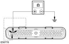
REFER to: Driver Air Bag Module (501-20B Supplemental Restraint System, Removal and Installation).
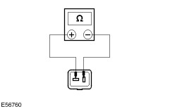
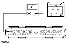
Test 1 Hold the speed control switch in the ON position. Measure the resistance between pin 1 and pin 3. Is the resistance less than 830 ohms? If yes, continue with Test 2. If no, INSTALL a new speed control switch.
REFER to: Speed Control Switch (310-03 Speed Control, Removal and Installation).
TEST the system for normal operation. Test 2 Hold the speed control switch in the OFF position. Measure the resistance between pin 2 and pin 3. Is the resistance 0 ohms? If yes, continue with Test 3. If no, INSTALL a new speed control switch.
REFER to: Speed Control Switch (310-03 Speed Control, Removal and Installation).
TEST the system for normal operation. Test 3 Hold the speed control switch in the SET position. Measure the resistance between pin 2 and pin 3. Is the resistance less than 690 ohms? If yes, continue with Test 4. If no, INSTALL a new speed control switch.
REFER to: Speed Control Switch (310-03 Speed Control, Removal and Installation).
TEST the system for normal operation. Test 4 Hold the speed control switch in the RESUME position. Measure the resistance between pin 2 and pin 3. Is the resistance less than 2250 ohms? If yes, continue with Test 5. If no, INSTALL a new speed control switch.
REFER to: Speed Control Switch (310-03 Speed Control, Removal and Installation).
TEST the system for normal operation. Test 5 Hold the speed control switch in the DECELERATE position. Measure the resistance between pin 2 and pin 3. Is the resistance less than 120 ohms? If yes, INSTALL a new speed control module. TEST the system for normal operation. If no, INSTALL a new speed control switch.
REFER to: Speed Control Switch (310-03 Speed Control, Removal and Installation).
TEST the system for normal operation. |