| Diagnosis and Testing Refer to Wiring Diagrams Section 412-02B, for schematic and connector information. Special Tool(s) | | Terminal Probe Kit 418-S035 | General Equipment Digital Multimeter Worldwide Diagnostic System (WDS) Graduated vessel Inspection and Checking - Visually CHECK for any obvious mechanical or electrical damage.
Visual Inspection | Mechanical | Electrical | - Coolant level
- Combustion air line
- Exhaust gas pipe
- Fuel line - booster heater
- Fuel tank fill level
| - Fuses
- Wiring harness
- Connectors
| - RECTIFY any obvious causes for a concern found during the visual inspection before performing any further tests. CHECK the operation of the system.
-
NOTE:Ensure that the fuel-fired booster heater is switched on during fault diagnosis with WDS. If necessary, bridge the ambient temperature thermo switch. Observe the activation conditions,
REFER to: Fuel Fired Booster Heater (412-02B Auxiliary Heating, Description and Operation).
If the concern persists, PERFORM a fault diagnosis on the fuel fired booster heater and the charging system with WDS and RECTIFY any displayed faults in accordance with the displayed fault description. CHECK the operation of the system. - For vehicles with no stored faults, PROCEED in accordance with the Symptom Chart according to the fault symptom.
- Following checking or elimination of the fault and after completion of operations, the fault memories of all vehicle modules must be READ OUT and any stored faults must be DELETED. READ OUT all fault memories again following a road test.
Diagnostic Trouble Code (DTC) index | Diagnostic Trouble Code | Conditions | Action | | B1317 | Battery voltage too high, voltage greater than 16 V (excess voltage applied for more than 20 seconds) | CHECK battery,
REFER to: Battery (414-01 Battery, Mounting and Cables, Diagnosis and Testing).
| CHECK charging system,
REFER to: Generator (414-02 Generator and Regulator, Diagnosis and Testing).
| | B1318 | Battery voltage too low, voltage less than 10.2 V (undervoltage applied for more than 20 seconds) | CHECK battery,
REFER to: Battery (414-01 Battery, Mounting and Cables, Diagnosis and Testing).
| CHECK charging system,
REFER to: Generator (414-02 Generator and Regulator, Diagnosis and Testing).
| | If the battery and charging system are OK: GO to Pinpoint Test A. | | B1342 | Control module defective | Renew control module | | B2449 | Glow plug circuit, short to ground | GO to Pinpoint Test C. | | B2450 | Glow plug circuit, open circuit | GO to Pinpoint Test C. | | B2451 | Booster heater fuel pump circuit, short circuit to ground | GO to Pinpoint Test B. | | B2452 | Booster heater fuel pump circuit, open circuit | GO to Pinpoint Test B. | | B2453 | Combustion air blower motor circuit, short to ground | Check the combustion air blower motor according to the component check at the end of this section. | | B2454 | Combustion air blower motor circuit, open circuit | Check the combustion air blower motor according to the component check at the end of this section. | | B2455 | Combustion air blower motor speed outside the tolerance range | Check the combustion air blower motor according to the component check at the end of this section. | | B2456 | Temperature sensor circuit, short to ground | Check the temperature sensor according to the component check at the end of this section. | | B2457 | Temperature sensor circuit, open circuit | Check the temperature sensor according to the component check at the end of this section. | | B2458 | Overheating sensor circuit, short to ground | Check the overheating sensor according to the component check at the end of this section. | | B2459 | Overheating sensor circuit, open circuit | Check the overheating sensor according to the component check at the end of this section. | | B2460 | Flame sensor circuit, short to ground | Check the flame sensor according to the component check at the end of this section. | | B2461 | Flame sensor circuit, open circuit | Check the flame sensor according to the component check at the end of this section. | | B2462 | Flame extinguished during operation, attempt to restart failed | Check exhaust and combustion air pipes. | | Check fuel line of fuel fired booster heater. | | Check the booster heater fuel pump fuel quantity according to the component check at the end of this section. | | If combustion is OK, check the flame sensor according to the component check at the end of this section. | | B2463 | Overheating sensor triggered due to overheating | Check the cooling system: | | - Check the cooling system for leaks. | | - Check the cooling system for restrictions. | | - Bleed the cooling system. | | If the cooling system is OK, check the temperature sensor and the overheating sensor according to the component check at the end of this section. | | B2464 | Safety period exceeded | Check exhaust and combustion air pipes. | | Check the booster heater fuel pump fuel quantity according to the component check at the end of this section. | | B2465 | Operation lock, too many unsuccessful attempts at starting | Release the operation lock, delete the control module fault memory using WDS for this purpose. | | Check the booster heater fuel pump fuel quantity according to the component check at the end of this section. | | B2466 | Operation lock, permissible number of overheating incidents exceeded | Release the operation lock, delete the control module fault memory using WDS for this purpose. | | Check the cooling system: | | - Check the cooling system for leaks. | | - Check the cooling system for restrictions. | | - Bleed the cooling system. | | B2467 | Blower cooling time limit exceeded | A temperature exceeding 70°C is measured by the flame sensor for longer than 240 seconds when the booster heater is switched on. | | Check exhaust and combustion air pipes. | | Check the flame sensor according to the component check at the end of this section. | Symptom Chart Symptom Chart | Symptom | Possible Sources | Action | | Fuel-fired booster heater not communicating with the diagnostic unit | * Fuel fired booster heater not switched on * Fuse(s) * Circuit(s) * Control module | * Switch on the fuel fired booster heater. If necessary, bridge the ambient temperature thermo switch. Activation conditions
REFER to: Fuel Fired Booster Heater (412-02B Auxiliary Heating, Description and Operation).
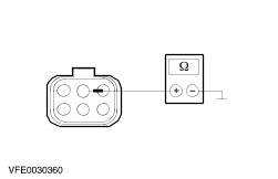
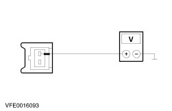
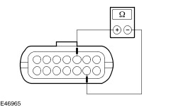
* REFER to: Communications Network (418-00 Module Communications Network, Diagnosis and Testing). | | Fuel fired booster heater inoperative | * Fuse(s) * Circuit(s) * Ambient temperature thermo switch * Control module | * | | Booster heater fuel pump inoperative | * Circuit(s) * Booster heater fuel pump | * | | Glow plug inoperative | * Circuit(s) * Glow plug | * | System checks | PINPOINT TEST A : FUEL FIRED BOOSTER HEATER INOPERATIVE | NOTE:The fuel fired booster heater only works when the engine is running (the battery is being charged by the generator), the ambient temperature is below 5°C and the coolant temperature has not yet exceeded 75°C. | NOTE:The fuel fired booster heater is equipped with an integrated undervoltage protection. This switches off the fuel fired booster heater when the supply voltage falls below 10 V for longer than 20 seconds. Before performing further checks, ensure that the charging system and the vehicle battery are OK. | | TEST CONDITIONS | DETAILS/RESULTS/ACTIONS | | A1: CHECK VEHICLE STATUS | | | 1 Check whether the vehicle has been equipped with the auxiliary wiring harness according to TSB no. 39/2002. | | | Does the vehicle conform to the above-mentioned status? Yes No | | A2: CHECK THE ADDITIONAL FUSE OF THE BOOSTER HEATER | | | 1 CHECK Additional fuse for the booster heater (near the ground connection of the battery). | | | Is the fuse OK? Yes No INSTALL NEW additional fuse for the booster heater (20 A). CHECK the operation of the system. If the fuse blows again, LOCATE and RECTIFY the short circuit using the Wiring Diagrams. | | A3: CHECK THE VOLTAGE AT THE ADDITIONAL FUSE FOR THE BOOSTER HEATER | | | 1 Connect Additional fuse for the booster heater (near the ground connection of the battery). | | | 2 Measure the voltage between the additional fuse for the booster heater (20 A) and ground. | | | Does the meter display battery voltage? Yes No REPAIR the voltage supply to the additional fuse for the booster heater using the Wiring Diagrams. CHECK the operation of the system. | | A4: CHECK FUSE F23 | | | 1 Ignition switch in position 0. | | | 2 CHECK fuse F23 (BJB). | | | Is the fuse OK? Yes No Fuse F23 (15 A) (vehicles built from 02/2003: 20 A) INSTALL NEW fuse. CHECK the operation of the system. If the fuse blows again, LOCATE and RECTIFY the short circuit using the Wiring Diagrams. | | A5: CHECK THE VOLTAGE AT FUSE F23 | | | 1 Connect fuse F23 (BJB). | | | 2 Measure the voltage between fuse F23 (15 A) (vehicles built from 02/2003: 20 A) and ground. | | | Does the meter display battery voltage? Yes No REPAIR the voltage supply to fuse F23 using the Wiring Diagrams. CHECK the operation of the system. | | A6: CHECK FUSE F82 | | | 1 CHECK fuse F82 (CJB). | | | Is the fuse OK? Yes No RENEW fuse F82 (7.5 A). CHECK the operation of the system. If the fuse blows again, LOCATE and RECTIFY the short circuit using the Wiring Diagrams. | | A7: CHECK THE VOLTAGE AT FUSE F82 | | | 1 Connect fuse F82 (CJB). | | | 2 Ignition switch in position II. | | | 3 Measure the voltage between fuse F82 (7.5 A) and ground. | | | Does the meter display battery voltage? Yes No REPAIR the voltage supply to fuse F82 using the Wiring Diagrams. CHECK the operation of the system. | | A8: CHECK THE VOLTAGE AT THE BOOSTER HEATER - PIN 1 | | | 1 Ignition switch in position 0. | | | 2 Disconnect Connector C252 from the booster heater. | | | 3 Measure the voltage between the booster heater, connector C252, pin 1, circuit 30-HA20 (RD), wiring harness side and ground. | | | Does the meter display battery voltage? Yes No LOCATE and RECTIFY the break in the circuit between the booster heater and fuse F23 or the auxiliary fuse for the booster heater using the Wiring Diagrams. CHECK the operation of the system. | | A9: CHECK THE VOLTAGE AT THE BOOSTER HEATER - PIN 4 | | | 1 Ignition switch in position II. | | | 2 Measure the voltage between the booster heater, connector C252, pin 4, circuit 15-HA20 (GN/WH), wiring harness side and ground. | | | Does the meter display battery voltage? Yes No | | A10: CHECK FOR OPEN CIRCUIT BETWEEN THE BOOSTER HEATER AND THE CJB | | | 1 Ignition switch in position 0. | | | 2 Disconnect Connector C509 from CJB. | | | 3 Measure the resistance between the CJB, connector C509, pin 15, circuit 15S-HA20 (GN/WH), wiring harness side and the booster heater, connector C252, pin 4, circuit 15-HA20 (GN/WH), wiring harness side. | | | Is a resistance of less than 2 Ohms registered? Yes CHECK the CJB and RENEW if necessary. CHECK the operation of the system. No LOCATE and REPAIR the break in the circuit between the booster heater and the CJB using the Wiring Diagrams. CHECK the operation of the system. | | A11: CHECK CONTROL VOLTAGE AT BOOSTER HEATER | | | 1 Cool ambient temperature thermo switch to a temperature of at least 5°C using a suitable medium. | | | 2 Ignition switch in position III. 3 Run the engine at idle speed. | | | NOTE:The charge warning indicator must no longer illuminate. 4 Measure voltage between booster heater, connector C252, pin 5, circuit 15S-BA9C (GN/BK), wiring harness side and ground. | | | Does the meter display battery voltage? Yes No | | A12: CHECK GROUND CONNECTION AT BOOSTER HEATER | | | 1 Ignition switch in position 0. | | | 2 Measure the resistance between the booster heater, connector C252, pin 2, circuit 31-HA20 (BK), wiring harness side and ground. | | | Is a resistance of less than 2 Ohm registered? Yes CHECK and if necessary RENEW the additional heater. CHECK the operation of the system. No LOCATE and RECTIFY the break in the circuit between the booster heater and ground connection G104 using the Wiring Diagrams. CHECK the operation of the system. | | A13: CHECK THE VOLTAGE AT THE AMBIENT TEMPERATURE THERMO SWITCH | | | 1 Ignition switch in position 0. | | | 2 Disconnect Connector C121 of the ambient temperature thermo switch. | | | 3 Ignition switch in position III. 4 Run the engine at idle speed. | | | NOTE:The charge warning indicator must no longer illuminate. 5 Measure the voltage between the ambient temperature thermo switch, connector C121, pin 2, circuit 15S-BA9B (GN/BK), wiring harness side and ground. | | | Is battery voltage measured? Yes No LOCATE and REPAIR the open circuit in circuit 15S-BA9B (GN/BK) between the ambient temperature thermo switch and soldered connection S333 using the Wiring Diagrams. CHECK the operation of the system. | | A14: CHECK FOR OPEN CIRCUIT BETWEEN THE AMBIENT TEMPERATURE THERMO SWITCH AND THE BOOSTER HEATER | | | 1 Ignition switch in position 0. | | | 2 Measure the resistance between the ambient temperature thermo switch, connector C121, pin 1, circuit 15S-BA9C (GN/BK), wiring harness side and the booster heater, connector 252, pin 5, circuit 15S-BA9C (GN/BK), wiring harness side. | | | Is a resistance of less than 2 Ohm registered? Yes RENEW the ambient temperature thermo switch. CHECK the operation of the system. No LOCATE and REPAIR the break in circuit 15S-BA9C (GN/BK) between the ambient temperature thermo switch and the booster heater using the Wiring Diagrams. CHECK the operation of the system. | | PINPOINT TEST B : BOOSTER HEATER FUEL PUMP INOPERATIVE | | TEST CONDITIONS | DETAILS/RESULTS/ACTIONS | | B1: CHECK THE CIRCUIT BETWEEN THE CONTROL MODULE AND THE FUEL PUMP OF THE BOOSTER HEATER FOR DAMAGE | | | 1 Check the wiring harness between the control module, connector C1066 and the fuel pump of the booster heater, connector C1075a for damage. | | | Is the wiring harness undamaged? Yes RENEW the booster heater fuel pump. CHECK the operation of the system. No LOCATE and REPAIR the damage/open circuit in the relevant circuit between the control module and the booster heater fuel pump. CHECK the operation of the system. | | PINPOINT TEST C : GLOW PLUG INOPERATIVE | CAUTION:Never apply 12 V to the glow plug. The glow plug is destroyed by voltages exceeding 8 V. | | TEST CONDITIONS | DETAILS/RESULTS/ACTIONS | | C1: CHECK THE GLOW PLUG. | | | 1 Disconnect Connector C1066 from control module. | | | 2 Measure the resistance at the control module, connector C1066, between pin 9 (WH) and pin 12 (BN), wiring harness side. | | | Is a resistance of less than 1 Ohms registered? Yes CHECK the wiring harness between the control module and the glow plug for damage and REPAIR if necessary. If the wiring harness is OK, RENEW the glow plug. CHECK the operation of the system. No | | C2: CHECK FOR OPEN CIRCUIT BETWEEN THE CONTROL MODULE AND THE GLOW PLUG. | | | 1 Disconnect connector C1061a and C1061b from the glow plug. | | | 2 Measure the resistance between the control module, connector C1066, pin 9 (WH), wiring harness side and the glow plug, connector C1061b (WH), wiring harness side. | | | 3 Measure the resistance between the control module, connector C1066, pin 12 (BN), wiring harness side and the glow plug, connector C1061a (BN), wiring harness side. | | | Is a resistance of less than 2 Ohms measured in both cases? Yes RENEW the glow plug. CHECK the operation of the system. No LOCATE and REPAIR the break in the relevant circuit between the control module and the glow plug using the Wiring Diagrams. CHECK the operation of the system. | Component Tests Combustion air blower motor CAUTION:Never apply 12 V to the combustion air blower motor. The combustion air blower motor is destroyed by voltages exceeding 8 V. - Combustion air blower motor speed not OK.
- CHECK the combustion air blower fanwheel and motor for ease of movement and soiling. Check for moisture, which can freeze at temperatures below 0° C. Ensure correct routing of the wiring harness. ELIMINATE stiffness or blockage, RENEW the combustion air blower motor if necessary.
- Combustion air blower motor, open/short circuit
- CHECK the combustion air blower motor wiring harness for damage and REPAIR, RENEW the combustion air blower motor if necessary.
- Measure the resistance between the control module, connector C1066, pin 13 (BK), wiring harness side and the combustion air blower motor housing.
- Measure the resistance between the control module, connector C1066, pin 14 (BN), wiring harness side and the combustion air blower motor housing.
- Is a resistance greater than 2,000 Ohms measured in both cases?
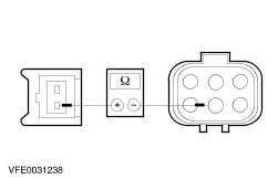
1. If yes, CHECK the combustion air blower fanwheel and motor for blockage. See above. 2. If no, RENEW the combustion air blower motor. Temperature sensor - CHECK the wiring (BU) to the temperature sensor for damage and RENEW the temperature sensor if necessary.
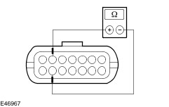
- Check the temperature sensor for a short to ground.
- Measure the resistance between the control module, connector C1066, pin 3 (BU), wiring harness side and the temperature sensor housing.
- Measure the resistance between the control module, connector C1066, pin 4 (BU), wiring harness side and the temperature sensor housing.
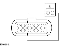
- Check the temperature sensor:
- Measure the resistance at the control module, connector C1066, between pin 3 and pin 4, wiring harness side.
- Compare the resistance value with the following table.
| Temperature | Resistance value | | 0 °C | 32.540 Ohm | | 10 °C | 19.870 Ohm | | 20 °C | 12.480 Ohm | | 30 °C | 8.060 Ohm | | 40 °C | 5.330Ohm | | 50 °C | 3.600 Ohm | | 60 °C | 2.480 Ohm | | 70 °C | 1.750 Ohm | | 80 °C | 1.250 Ohm | | 90 °C | 910 Ohm | | 100 °C | 670 Ohm | | 110 °C | 500 Ohm | | 120 °C | 380 Ohm | - Does the resistance measured correspond to the required value?
1. If yes, the temperature sensor is OK. 2. If no, RENEW the temperature sensor. Overheating sensor - CHECK the wiring (RD) to the overheating sensor for damage and RENEW the overheating sensor if necessary.
- Check the overheating sensor for a short to ground.
- Measure the resistance between the control module, connector C1066, pin 5 (RD), wiring harness side and the overheating sensor housing.
- Measure the resistance between the control module, connector C1066, pin 6 (RD), wiring harness side and the overheating sensor housing.
- Check the overheating sensor:
- Measure the resistance at the control module, connector C1066, between pin 5 and pin 6, wiring harness side.
- Compare the resistance value with the following table.
| Temperature | Resistance value | | 0 °C | 32.540 Ohm | | 10 °C | 19.870 Ohm | | 20 °C | 12.480 Ohm | | 30 °C | 8.060 Ohm | | 40 °C | 5.330Ohm | | 50 °C | 3.600 Ohm | | 60 °C | 2.480 Ohm | | 70 °C | 1.750 Ohm | | 80 °C | 1.250 Ohm | | 90 °C | 910 Ohm | | 100 °C | 670 Ohm | | 110 °C | 500 Ohm | | 120 °C | 380 Ohm | - Does the resistance measured correspond to the required value?
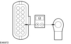
1. If yes, the overheating sensor is OK. 2. If no, RENEW the overheating sensor. Flame sensor - CHECK the wiring to the flame sensor for damage and RENEW the flame sensor if necessary.
- Check the flame sensor for short to ground.
- Measure the resistance between the control module, connector C1066, pin 1 (BU), wiring harness side and the flame sensor housing.
- Measure the resistance between the control module, connector C1066, pin 2 (BN), wiring harness side and the flame sensor housing.
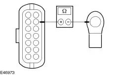
- Check the flame sensor:
- Measure the resistance at the control module, connector C1066, between pin 1 and pin 2, wiring harness side.
- Compare the resistance value with the following table.
| Temperature | Resistance value | | 0 °C | 1000 Ohm | | 10 °C | 1022 Ohm | | 20 °C | 1062 Ohm | | 30 °C | 1097 Ohm | | 50 °C | 1194 Ohm | | 80 °C | 1309 Ohm | | 90 °C | 1347 Ohm | | 100 °C | 1385 Ohm | | 130 °C | 1498 Ohm | | 150 °C | 1573 Ohm | | 200 °C | 1758 Ohm | | 250 °C | 1941 Ohm | | 300 °C | 2120 Ohm | | 350 °C | 2297 Ohm | | 400 °C | 2470 Ohm | - Does the resistance measured correspond to the required value?
1. If yes, the flame sensor is OK. 2. If no, RENEW the flame sensor. Check the fuel quantity of the booster heater fuel pump NOTE:For the measurement, it must be ensured that the voltage at the booster heater is between 11 V and 13 V during the measurement, as otherwise the measurement result will be incorrect. Preparations for measuring the fuel quantity Disconnect the fuel line between the booster heater fuel pump and the heater at the heater. Lengthen the fuel line if necessary. Insert the free end of the fuel line into a suitable graduated vessel. Start the engine and allow it to idle. (Pay attention to the activation conditions of the fuel fired booster heater
REFER to: Fuel Fired Booster Heater (412-02B Auxiliary Heating, Description and Operation).
) If necessary, bridge the ambient temperature thermo switch. Fuel delivery begins approx. 45 seconds after the fuel fired booster heater is switched on. If the fuel escapes from the fuel line without air bubbles, switch off the fuel fired booster heater again and empty the graduated vessel. Measure the fuel quantity Start the engine and allow it to idle. (Observe the activation conditions of the fuel fired booster heater
REFER to: Fuel Fired Booster Heater (412-02B Auxiliary Heating, Description and Operation).
) Fuel delivery begins after approx. 45 seconds. NOTE:The end of the hose must be held at the height of the heater during the measurement. Fuel delivery ends automatically after approx. 90 seconds. Switch off the fuel fired booster heater. The fuel quantity delivered should be between 7.5 cm³ and 8.6 cm³. If the fuel quantity is outside the range given for the delivery quantity, renew the fuel pump for the booster heater. |