| Removal and Installation | | -
Remove the facia crash padding.
For additional information, refer to: Instrumententafel (501-12, Removal and Installation).
| 2. Remove the components in the order indicated in the following illustration(s) and table(s). 2 - Screw clips - left-hand door sill trim 3 - Screws - left-hand door sill trim 4 - Clips - left-hand door sill trim 5 - Left-hand door sill trim 7 - Bracket - CJB connector 3. To install, reverse the removal procedure. Removal Details Item 1 : Left-hand lower trim - B-pillar | | -
Carefully pull the B-pillar trim forwards until the door sill trim screw clips are accessible. | Item 6 : Relay - central junction box (CJB) | | -
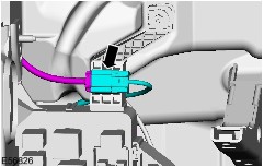
Detach the overhead console wiring harness connector and detach the socket from the CJB. | | | -
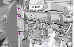
Remove the in-vehicle crossbeam left-hand retaining bolts. | | | -
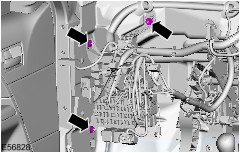
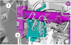
Detach the CJB from the bulkhead. - Pull the reinforcing element rearwards.
- Remove the CJB.
| |