| PINPOINT TEST C : A SINGLE POWER WINDOW IS INOPERATIVE - FRONT AND REAR POWER WINDOWS - REAR PASSENGER POWER WINDOW |
| TEST CONDITIONS | DETAILS/RESULTS/ACTIONS |
| C1: CHECK THE INOPERATIVE WINDOW FOR OPERATION FROM THE DRIVER POWER WINDOW CONTROL SWITCH |
| | 1 Ignition switch in position II. |
| | 2 Operate the driver power window control switch. |
| | Does the inoperative rear passenger power window operate correctly? Yes No |
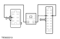
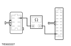
| C2: CHECK FOR CONTINUITY BETWEEN THE INOPERATIVE PASSENGER POWER WINDOW CONTROL SWITCH AND THE MOTOR DOWN CIRCUIT |
| | 1 Ignition switch in position 0. |
| | 2 Disconnect Driver Power Window Control Switch C709. |
| | 3 Disconnect Inoperative Passenger Power Window Control Switch C711 or C712. |
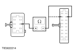
| | 4 Measure the resistance between: |
| | Is the resistance less than 5 ohms? Yes No REPAIR circuit 31S-AJ63A (BK/BU). TEST the system for normal operation. |
| C3: CHECK FOR CONTINUITY BETWEEN THE INOPERATIVE PASSENGER POWER WINDOW CONTROL SWITCH AND THE MOTOR UP CIRCUIT |
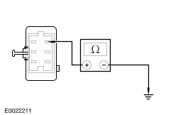
| | 1 Measure the resistance between |
| | Is the resistance less than 5 ohms? Yes VERIFY the customer concern. No REPAIR circuit 31S-AJ64A (BK/OG). TEST the system for normal operation. |
| C4: CHECK FOR VOLTAGE TO THE INOPERATIVE PASSENGER POWER WINDOW CONTROL SWITCH |
| | 1 Ignition switch in position II. |
| | Does the inoperative passenger power window control switch LED illuminate? Yes No |
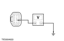
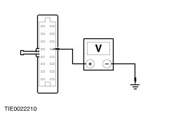
| C5: CHECK FOR BATTERY VOLTAGE TO THE INOPERATIVE PASSENGER POWER WINDOW MOTOR |
| | 1 Ignition switch in position 0. |
| | 2 Disconnect Inoperative Passenger Power Window Motor C707 or C708. |
| | 3 Ignition switch in position II. |
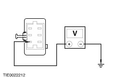
| | 4 Measure the voltage between: |
| | Is the voltage greater than 10 volts? Yes No REPAIR circuit 29-AJ31 (OG/BU). TEST the system for normal operation. |
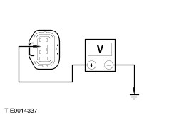
| C6: CHECK FOR IGNITION VOLTAGE TO THE INOPERATIVE PASSENGER POWER WINDOW MOTOR |
| | 1 Measure the voltage between: |
| | Is the voltage greater than 10 volts? Yes No REPAIR circuit 15-AJ31 (GN/BU). TEST the system for normal operation. |
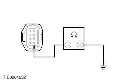
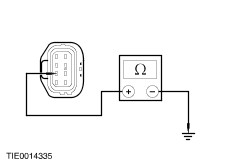
| C7: CHECK FOR CONTINUITY BETWEEN THE INOPERATIVE PASSENGER POWER WINDOW MOTOR AND GROUND |
| | 1 Ignition switch in position 0. |
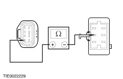
| | 2 Measure the resistance between: |
| | Is the resistance less than 5 ohms? Yes No REPAIR circuit 31-AJ31 (BK). TEST the system for normal operation. |
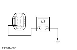
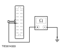
| C8: CHECK FOR CONTINUITY BETWEEN THE INOPERATIVE PASSENGER POWER WINDOW MOTOR DOWN CIRCUIT AND GROUND |
| | 1 Disconnect Inoperative Passenger Power Window Control Switch C711 or C712. |
| | 2 Operate and hold the inoperative passenger power window motor control switch in the DOWN position. |
| | 3 Measure the resistance between: |
| | Is the resistance less than 5 ohms? Yes No REPAIR circuit 31S-AJ63 (BK/BU). TEST the system for normal operation. |
| C9: CHECK FOR CONTINUITY BETWEEN THE INOPERATIVE PASSENGER POWER WINDOW MOTOR UP CIRCUIT AND GROUND |
| | 1 Operate and hold the inoperative passenger power window motor control switch in the UP position. |
| | 2 Measure the resistance between: |
| | Is the resistance less than 5 ohms? Yes INSTALL a new motor. REFER to the procedure in this Section: Door Window Regulator and Motor. TEST the system for normal operation. No REPAIR circuit 31S-AJ64 (BK/OG). TEST the system for normal operation. |
| C10: CHECK THE INOPERATIVE PASSENGER POWER WINDOW CONTROL SWITCH GROUND CIRCUIT |
| | 1 Ignition switch in position 0. |
| | 2 Disconnect Inoperative Passenger Power Window Control Switch C711 or C712. |
| | 3 Measure the resistance between: |
| | Is the resistance less than 5 ohms? Yes No REPAIR circuit 31S-AJ32 (BK/OG). TEST the system for normal operation. |
| C11: CHECK FOR IGNITION VOLTAGE TO THE INOPERATIVE PASSENGER POWER WINDOW CONTROL SWITCH |
| | 1 Ignition switch in position II. |
| | 2 Measure the voltage between: |
| | Is the voltage greater than 10 volts? Yes VERIFY the customer concern. No REPAIR circuit 15-LH36 (GN/RD). TEST the system for normal operation. |