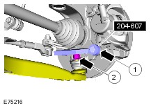
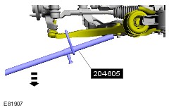
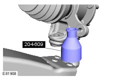
| Removal and Installation Special Tool(s) | | 204-159 Lever, Wheel Knuckle | | | 204-605 Separator, Lower arm-ball joint | | | 204-607 Remover, Ball joint | | | 204-609 Protection Cap, Ball Joint Gaiter | Removal NOTE:Removal steps in this procedure may contain installation details. | | -
Loosen the wheel hub bolt. | | | -
Remove the wheel and tire. Refer to: Wheel and Tire (204-04 Wheels and Tires, Removal and Installation). | Vehicles with high intensity discharge headlamps Vehicles with dynamic suspension All vehicles | | -
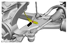
CAUTION:Make sure that the ball joint ball does not rotate. Loosen the tie-rod end nut. | | | -
WARNING:Make sure that a new nut is installed. CAUTION:Use suitable packing material to prevent damage to the component. CAUTION:Make sure that the ball joint ball does not rotate. | | | -
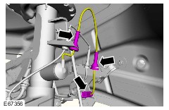
WARNING:Make sure that no load is placed on the brake hose. -
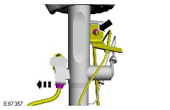
Loosen the nut two turns. Torque: 100 Nm | | | -
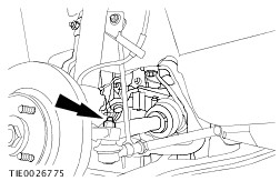
CAUTION:If the outer constant velocity (CV) joint boot is damaged a new halfshaft must be installed. Torque: Stage 1: 45 Nm Stage 2: 80° | Installation | | -
To install, reverse the removal procedure. | |