ford Workshop Repair Guides

Ford Workshop Service and Repair Manuals

412-02 Auxiliary Climate Control|Removal and Installation > < Electric Booster Heater
Auxiliary Climate Control - Fuel Fired Booster Heater Mondeo 2007.5 (02/2007-)
Description and Operation

Principles of Operation

The fuel-fired booster heater provides extra heat to the passenger compartment if the heat given off by the engine is not sufficient (boost heater function).

By burning fuel, the fuel-fired booster heater generates heat which is conveyed via the coolant circuit to the engine and the passenger compartment.

Functional illustration

 
Item
Part Number
Description
1
-
Engine
2
-
Fuel pump
3
-
Fuel tank
4
-
Heater core with blower motor
5
-
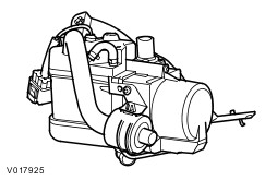
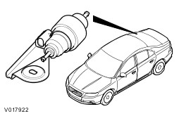
Fuel fired booster heater
6
-
Air Intake
7
-
Exhaust pipe
8
-
Water pump

Boost heat mode

When the engine is running, the fuel-fired booster heater assists the engine in heating up the passenger compartment at low ambient temperatures, if the vehicle has an engine that gives off only a small amount of heat.

When the coolant temperature reaches 30°C, the control unit transmits a switch-on signal for the passenger compartment blower via the CAN bus. When the coolant temperature drops, the blower remains on until the temperature reaches 20°C whereupon it is deactivated.

The fuel tank must be filled to at least 14% for the system to be switched on. If the fuel level drops below 8% then the system is switched off.

    In boost mode, the fuel-fired booster heater is only switched on if all of the following criteria are met:

  • Engine speed above 500 rev/min. The fuel-fired booster heater is not allowed to start up while the engine is being cranked; this prevents a shut-down due to low voltage if the battery charge is low.
  • Ambient temperature below 5°C
  • Fuel level above 14% of total capacity.
  • Function is active on the trip computer menu.

    The presence of one of the following conditions is enough to cause the fuel-fired booster heater to be deactivated:

  • Engine speed below 500 rpm.
  • Ambient temperature above 11°C
  • Function is active on the trip computer menu.
  • Fuel level below 8% of total capacity.

Fuel powered booster heater with additional parking heater function

The fuel powered booster heater with additional parking heater function has two modes of operation: immediate start-up and programmed start-up.

The heater status is displayed on the instrument cluster display. The parking heater mode is controlled via a menu on the driver information system. The fuel-fired booster heater can be activated and deactivated via the driver information system. (If set to '"Auto" the system is activated, if set to "Off" the system is completely deactivated.) The system is operated from a control menu on the steering wheel.

Immediate start-up of the fuel powered booster heater

This function enables the fuel-fired booster heater to be switched on manually when the engine is not running. The function is activated using the steering wheel control menu in the driver information system.

The ignition key must be in the II" position before this menu can be accessed. The timer function for the fuel powered booster heater remains active when the ignition key is in position "0".

After an immediate start-up of the fuel powered booster heater it is switched off again after 30 minutes (or if the fuel level in the fuel tank drops below 8%). The fuel powered booster heater stops within 2 minutes of the engine starting. This leaves enough time to check whether the switch-on conditions for boost heat mode have been met, thus preventing the fuel powered booster heater from having to switch off and switch back on again. The heater can be switched off manually at any time from the menu.

Programmed start-up of the fuel powered booster heater

    The driver can use a menu to adjust the time at which the vehicle is to be pre-heated. The following options are available:

  • Time setting. One or two times can be programmed for each day of the week. It is possible to program days either individually or together in groups (Mon-Sun/Mon-Sat/Mon-Fri).
  • Time and data setting

With the first option, the fuel-fired booster heater will start repeatedly without needing to be reprogrammed. However, if the engine has not been running since the last programmed start, the fuel powered booster heater will not start up a second time to prevent the battery from being discharged.

    The length of time required to pre-heat the vehicle is calculated in the control unit of the fuel-fired booster heater and is based on two temperature values:

  • Ambient air temperature: this message is taken from the Generic Electronic Module (GEM) via the CAN bus.
  • Coolant temperature: this is determined via an internal sensor in the fuel-fired booster heater.

The maximum heating time is 30 minutes at an outside air temperature of -10°C or lower. The heating time decreases proportionally as the ambient temperature increases until the ambient temperature is +15°C. Then the minimum heating time is 10 minutes. The parking heater is deactivated at temperatures above +15°C.

    The sequence for a programmed start of the fuel powered booster heater is as follows:

  • Two minutes before the start of the maximum heating time the driver information system/instrument cluster sends an activation message to the fuel-fired booster heater via the CAN bus.
  • The fuel-fired booster heater calculates the required heating time and, if necessary, sends a delay request on the CAN bus.
  • At the calculated time, the fuel-fired booster heater starts up. The conditions for start-up are: engine not running and amount of fuel in the fuel tank is above 14% of maximum.
  • When the coolant temperature reaches +30°C , the fuel powered booster heater module sends a request to switch on the passenger compartment blower.
  • Eight minutes after the programmed switch-off time, the fuel powered booster heater stops heating mode and starts a run-on operation to clean the system's spark plugs.
  • Ten minutes after the switch-off time, the post-cleaning operation is complete. The additional ten minutes run-on time provides some leeway in case the driver is late arriving.

After a programmed start-up of the fuel powered booster heater, it is switched off again after the heating time has elapsed (or if the fuel level in the fuel tank drops below 8%). The fuel powered booster heater stops within 2 minutes of the engine starting. This leaves enough time to check whether the switch-on conditions for boost heat mode have been met, thus preventing the fuel powered booster heater from having to switch off and switch back on again. The heater can be switched off manually at any time from the menu.

Whilst the fuel-fired booster heater is in additional heating mode and/or parking heating mode, the instrument cluster receives a fuel consumption signal; this is used to re-calculate the vehicle's remaining range and fuel consumption data.

Emergency shutoff

In the event of an accident in which the airbags are deployed, the fuel powered booster heater module receives a message on the CAN bus from the restraints control module (RCM). When this signal is received, the fuel powered booster heater system is immediately deactivated .

The fuel powered booster heater module deactivates the system and does not respond to further messages on the CAN bus. The fuel powered booster heater module needs to be activated with the diagnostic unit.

Initial operation

The fuel powered booster heater needs to be filled before being operated for the first time. Activation of the fuel pump for the fuel powered booster heater is controlled by the diagnostic unit.

Fuel powered booster heater

    The fuel powered booster heater has the following internal electrical components:

  • Fuel-fired additional heater control module
  • Combustion air blower
  • Glow plug
  • Water temperature sender unit
  • Overheating sensor
  • Fuel preheater (diesel vehicles only)

    The fuel powered booster heater has the following external electrical components:

  • Water pump
  • Fuel pump
  • Remote start equipment (special accessory)

Fuel-fired additional heater control module

The fuel powered booster heater module is fitted with an external central connector for connecting it to the vehicle, a coolant pump and a fuel pump. The other 3 connectors are covered by a plastic cover and are used for the internal electrical components. The blower motor is connected directly to the fuel powered booster heater module board from underneath with 2 pins. The fuel powered booster heater module receives signals from the individual temperature sensors and other components. Based on this data, the fuel powered booster heater module controls its start-up, power and switch off. The fuel powered booster heater module constantly monitors whether faults occur in the system during operation and saves these as fault codes.

Water pump

The coolant pump is located to the rear of the engine compartment near the bulkhead. The coolant pump is powered by a built-in electric motor and circulates the cooling fluid in the engine cooling system.

Fuel pump

The fuel pump is an electric reciprocating pump that meters the correct quantity of fuel for the fuel powered booster heater. The power supply for the fuel pump is connected to the fuel powered booster heater module. By pulsing the voltage supply at a varying frequency, the fuel powered booster heater module can regulate the quantity of fuel supplied for combustion. The fuel pump is located on the rear axle assembly close to the fuel tank and is connected to the fuel tank by a separate tank connection without a filter.

ECT sensor

The fuel powered booster heater module uses the coolant temperature sensor to determine the coolant temperature, which it then uses to set the starting and stopping time. The coolant temperature sensor is installed next to the overheating sensor below a cover on the underside of the fuel powered booster heater.

Overheating sensor

The overheating sensor enables the fuel powered booster heater module to determine the coolant temperature, protecting the heater from overheating. The overheating sensor is installed next to the coolant temperature sensor below a cover on the underside of the fuel powered booster heater.

Glow plug

The glow plug is positioned in such a way that one section protrudes into the combustion chamber. It has a wire that starts to glow when it draws current from the fuel powered booster heater module. The flow plug is activated by the fuel powered booster heater module and ignites the fuel/air mixture in the combustion chamber. The fuel powred booster heater module also uses the glow plug to detect combustion in the combustion chamber. The signal from the glow plug is also used to switch off the fuel powered booster heater.

Combustion air blower

The combustion air blower draws in air from the air intake and forces it into the combustion chamber during combustion. The combustion air blower is built into the heater and is positioned below the fuel powered booster heater module.

Fuel preheater (diesel vehicles only)

The fuel preheater is used to preheat the fuel in diesel vehicles to make it thinner in cold weather conditions. The heating coil in the fuel preheater is built into the heater next to the glow plug and is controlled by a pulse width modulated (PWM) signal.

Remote start equipment

    The remote start equipment consists of:

  • Hand-held transmitter
  • Power Control Module
  • Receiver (aerial)
  • Harness

The control unit is fitted on the passenger side A pillar behind the lower footwell cover. The receiver is located in the upper right-hand corner of the windshield (left-hand corner on right-hand drive vehicles) and is connected to the control unit by a coaxial cable. The remote start unit is connected to the fuel powered booster heater by the existing pre-laid wiring harness. The remote start control unit communicates with the fuel powered booster heater by serial communication in line with the supplier standard. The hand-held transmitter is powered by two 12V batteries, type MN21/23. A maximum of three hand-held transmitters can be programmed.

412-02 Auxiliary Climate Control|Removal and Installation > < Electric Booster Heater