| Diagnosis and Testing Refer to Wiring Diagrams Section 415-00, for schematic and connector information. Ford approved diagnostic tool Inspection and Verification - Verify the customer concern.
- Visually inspect for obvious signs of mechanical or electrical damage.
Visual Inspection Chart | Mechanical | Electrical | - Audio unit
- Antenna
- Foreign objects contacting speaker
- Trim poorly fitted/resonance
- Audio control switch (if equipped)
- Digital versatile disc (DVD) player
- Compact disc (CD) changer
| - Fuse(s)
- Wiring harness
- Electrical connector(s)
- Audio unit
- Audio control switch (if equipped)
- Generic electronic module (GEM)
- Video display
- DVD player
- CD changer
- Auxiliary input device
| - If an obvious cause for an observed or reported concern is found, correct the cause (if possible) before proceeding to the next step.
- If the cause is not visually evident, verify the symptom and refer to the Self-Diagnostic Mode.
Self-Diagnostic Mode - Low Series Audio Unit NOTE:The audio unit must be in radio mode before entering the Self-Diagnostic Mode. - To enter the audio unit Self-Diagnostic Mode, switch the audio unit ON. Within four seconds press the preset buttons 3 and 6 together.
- Release the preset buttons 3 and 6 and the audio unit will enter the Self-Diagnostic Mode.
- To exit the Self-Diagnostic Mode, switch the audio unit OFF.
Self-Diagnostic Mode | Message Displayed | Circuit Tested | | 1. 4CH LF for four channel system 2CH LF for two channel system | Left hand front speaker circuit | | 2. 4CH RF for four channel system 2CH RF for two channel system | Right hand front speaker circuit | | 3. 4CH LR for four channel system | Left hand rear speaker circuit | | 4. 4CH RR for four channel system | Right hand rear speaker circuit | | 5. XX.X (frequency) SEEKING | Antenna cable | | 6. XXXXXXXX (name of radio station) | Active FM frequency radio station found (audible for 2 seconds) | - Retrieve the Diagnostic Trouble Code (DTC)s and refer to the DTC Index Chart.
Self-Diagnostic Mode - High Series Audio Unit NOTE:The audio unit must be in radio mode before entering the Self-Diagnostic Mode. - To enter the audio unit Self-Diagnostic Mode, switch the audio unit ON. Within four seconds press the preset button 4 and TA together.
- Release the preset button 4 and TA and the audio unit will enter the Self-Diagnostic Mode.
- To exit the Self-Diagnostic Mode, switch the audio unit OFF.
Self-Diagnostic Mode | Message Displayed | Circuit Tested | | 1. 4CH LF for four channel system 2CH LF for two channel system | Left hand front speaker circuit | | 2. 4CH RF for four channel system 2CH RF for two channel system | Right hand front speaker circuit | | 3. 4CH LR for four channel system | Left hand rear speaker circuit | | 4. 4CH RR for four channel system | Right hand rear speaker circuit | | 5. XX.X (frequency) SEEKING | Antenna cable | | 6. XXXXXXXX (name of radio station) | Active FM frequency radio station found (audible for 2 seconds) | - Retrieve the Diagnostic Trouble Code (DTC)s and refer to the relevant DTC Index Chart.
Diagnostic Trouble Code (DTC) Index Chart - Low Series Audio Unit | DTC | Description/Condition | Possible Source | Action | | B1342 | Audio unit internal failure | Audio unit | INSTALL a new audio unit.
REFER to: Audio Unit (415-01 Information and Entertainment System, Removal and Installation).
| | B2403 | CD player internal failure | Audio unit | INSTALL a new audio unit.
REFER to: Audio Unit (415-01 Information and Entertainment System, Removal and Installation).
| | B2404 | Audio control switch circuit failure | Audio control switch | GO to Pinpoint Test G. | | B2406 | CD player internal failure | Audio unit | INSTALL a new audio unit.
REFER to: Audio Unit (415-01 Information and Entertainment System, Removal and Installation).
| | B2408 | Speaker line short circuit | Speaker(s) | GO to Pinpoint Test E. | | B2409 | AM receiving signal error | Antenna cable | GO to Pinpoint Test B. | | B2410 | FM receiving signal error | Antenna cable | GO to Pinpoint Test B. | | B2477 | Module configuration failure | Audio unit and GEM | REFER to the Ford approved diagnostic tool. | | P1628 | Module ignition supply input | GEM | REFER to the Ford approved diagnostic tool. | Diagnostic Trouble Code (DTC) Index Chart - High Series Audio Unit | DTC | Description/Condition | Possible Source | Action | | $U3000 | Audio unit internal failure | Audio unit | INSTALL a new audio unit.
REFER to: Audio Unit (415-01 Information and Entertainment System, Removal and Installation).
| | $B1A01 | Speaker line short circuit | Speaker(s) | GO to Pinpoint Test E. | | $U2100 | Module configuration failure | Audio unit and central junction box (CJB) | REFER to the Ford approved diagnostic tool. | | $U2101 | Module configuration failure | Audio unit and central junction box (CJB) | REFER to the Ford approved diagnostic tool. | | $U0155 | Lost communication with instrument cluster | Controller area network (CAN) | REFER to: Communications Network (418-00, Diagnosis and Testing). | | $U0238 | Lost communication with voice recognition module | CAN | REFER to: Communications Network (418-00, Diagnosis and Testing). | | $U0187 | Lost communication with CD changer | CAN | REFER to: Communications Network (418-00, Diagnosis and Testing). | | $U0140 | Lost communication with GEM | CAN | REFER to: Communications Network (418-00, Diagnosis and Testing). | | $B10BC | Audio control switch circuit failure | Audio control switch | GO to Pinpoint Test G. | - If the cause is still not evident or no DTCs are retrieved, refer to the Symptom Chart.
Symptom Chart | Symptom | Possible Sources | Action | | The audio unit is inoperative/does not operate correctly | * Circuit(s). * Audio unit. | * | | The audio unit display is blank - radio and CD player operate | * Audio unit. | * INSTALL a new audio unit.
REFER to: Audio Unit (415-01, Removal and Installation).
| | Poor reception | * Antenna. * Antenna cable. * Audio unit. | * | | Poor quality/distorted sound from one or more speakers (not all speakers) | * Speaker(s). * Circuit(s). * Audio unit. | * For concern with the main speakers, GO to Pinpoint Test C. * For concern with the tweeter speakers, GO to Pinpoint Test D. | | No sound from all speakers | * Audio unit. | * INSTALL a new audio unit.
REFER to: Audio Unit (415-01, Removal and Installation).
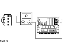
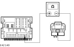
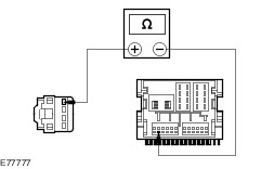
TEST the system for normal operation. | | No sound from one or more of the speakers (not all speakers) | * Speaker(s). * Circuit(s). * Audio unit. | * For concern with the main speakers, GO to Pinpoint Test E. * For concern with the tweeter speakers, GO to Pinpoint Test F. | | The auxiliary audio control is inoperative/does not operate correctly. | * Circuit(s). * Auxiliary audio control switch. * Audio unit. | * | | The CD changer is inoperative/does not operate correctly | * Circuit(s). * CD changer. | * | | The audio unit illumination is inoperative | * Circuit(s). * Audio unit. * GEM. | * REFER to: Instrument Cluster and Panel Illumination (413-00, Diagnosis and Testing). | | The auxiliary input device is inoperative/does not operate correctly | * Auxiliary input device. | * REFER the customer to the auxiliary input source supplier. | | * Circuit(s). * Audio unit. | * | | The DVD player is inoperative/does not operate correctly | * Contaminated DVD disc(s). | * CLEAN the DVD disc(s) using lint free material. TEST the system for normal operation. | | * Circuit(s). * DVD player. | * | | The video display is inoperative/does not operate correctly | * Contaminated DVD disc(s). | * CLEAN the DVD disc(s) using lint free material. TEST the system for normal operation. | | * Circuit(s). * Video display. | * | | * DVD player. | * | Pinpoint Tests NOTE:Use a digital multimeter for all electrical measurements. | PINPOINT TEST A : THE AUDIO UNIT IS INOPERATIVE/DOES NOT OPERATE CORRECTLY | | TEST CONDITIONS | DETAILS/RESULTS/ACTIONS | | A1: CHECK FOR POWER TO THE AUDIO UNIT | | | 1 Disconnect Audio Unit C2ME03A. | | | 2 Ignition switch in position I. | | | 3 Measure the voltage between the audio unit C2ME03A pin 15, circuit SBP06D (BN/RD), harness side and ground, and between the audio unit C2ME03A pin 16, circuit CDC33C (VT/GN), harness side and ground. | | | Are the voltages greater than 10 volts? Yes No REPAIR circuit SBP06D (BN/RD) or circuit CDC33C (VT/GN). TEST the system for normal operation. | | A2: CHECK THE AUDIO UNIT GROUND CIRCUITS FOR GROUND | | | 1 Ignition switch in position 0. | | | 2 Measure the resistance between the audio unit C2ME03A pin 11, circuit GD103C (BK/BU), harness side and ground, and between the audio unit C2ME03A pin 12, circuit GD103A (BK/BU), harness side and ground. | | | Are the resistances less than 1 ohm? Yes INSTALL a new audio unit.
REFER to: Audio Unit (415-01, Removal and Installation).
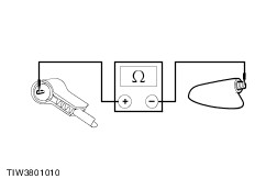
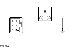
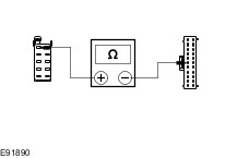
TEST the system for normal operation. No REPAIR circuit GD103C (BK/BU) or circuit GD103A (BK/BU). TEST the system for normal operation. | | PINPOINT TEST B : POOR RECEPTION | | TEST CONDITIONS | DETAILS/RESULTS/ACTIONS | | B1: CHECK THE ANTENNA CABLE SHIELD | | | 1 Ignition switch in position 0. | | | 2 Disconnect the antenna cable from the audio unit. | | | 3 Measure the resistance between the antenna cable ground connector (shield), and ground. | | | Is the resistance less than 1 ohm? Yes No CLEAN and TIGHTEN the antenna base connection to the body. If the concern persists, INSTALL a new antenna cable. TEST the system for normal operation. | | B2: CHECK THE ANTENNA CENTER CONDUCTOR FOR OPEN CIRCUIT | | | 1 Remove the antenna mast. | | | 2 Measure the resistance of the center conductor between the ends of the antenna cable. | | | Is the resistance less than 1 ohm? Yes No INSTALL a new antenna cable. TEST the system for normal operation. | | B3: CHECK THE ANTENNA CABLE FOR SHORT | | | 1 Measure the resistance between the antenna cable center conductor and the antenna ground (shield). | | | Is the resistance greater than 10,000 ohms (open circuit)? Yes CLEAN and TIGHTEN the ground connections at the base of the antenna and battery negative cable to the body. If the concern persists, INSTALL a new antenna cable. No INSTALL a new antenna cable. TEST the system for normal operation. If the concern persists, INSTALL a new audio unit.
REFER to: Audio Unit (415-01, Removal and Installation).
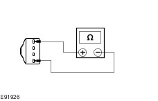
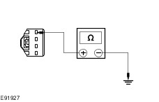
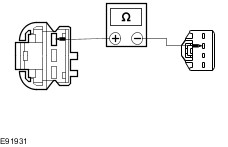
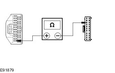
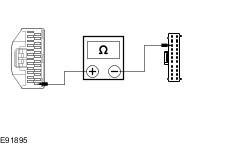
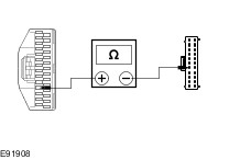
| | PINPOINT TEST C : POOR QUALITY/DISTORTED SOUND FROM ONE OR MORE MAIN SPEAKERS (NOT ALL SPEAKERS) | | TEST CONDITIONS | DETAILS/RESULTS/ACTIONS | | C1: CHECK THE SPEAKER RESISTANCE | | | 1 Disconnect Affected Speaker. | | | 2 Measure the resistance between pins 1 and 4 of the affected speaker(s), component side. | | | Is the resistance approximately 4.0 ohms? Yes No INSTALL a new speaker. TEST the system for normal operation. | | C2: CHECK SPEAKER INPUT FOR SHORT TO GROUND | | | 1 Disconnect Audio Unit C2ME03D. | | | 2 Measure the resistance between affected speaker connector pin 1, harness side and ground. | | | Is the resistance greater than 10,000 ohms (open circuit)? Yes No REPAIR speaker input circuit. TEST the system for normal operation. | | C3: CHECK SPEAKER RETURN FOR SHORT TO GROUND | | | 1 Measure the resistance between affected speaker connector pin 4, harness side and ground. | | | Is the resistance greater than 10,000 ohms (open circuit)? Yes INSTALL a new speaker. TEST the system for normal operation. If the concern persists, INSTALL a new audio unit.
REFER to: Audio Unit (415-01, Removal and Installation).
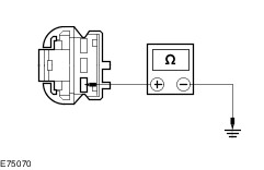
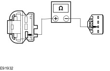
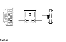
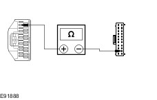
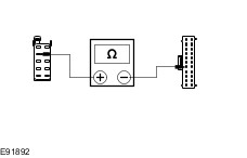
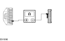
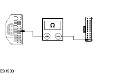
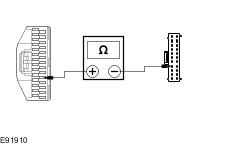
No REPAIR speaker return circuit. TEST the system for normal operation. | | PINPOINT TEST D : POOR QUALITY/DISTORTED SOUND FROM ONE OR MORE TWEETER SPEAKERS (NOT ALL SPEAKERS) | | TEST CONDITIONS | DETAILS/RESULTS/ACTIONS | | D1: CHECK THE SPEAKER INPUT FOR SHORT TO GROUND | | | 1 Disconnect Affected Tweeter Speaker. | | | 2 Disconnect Related Speaker Of Affected Tweeter Speaker. | | | 3 Measure the resistance between affected rear tweeter speaker connector pin 1, harness side and ground. | | | Is the resistance greater than 10,000 ohms (open circuit)? Yes No REPAIR speaker input circuit. TEST the system for normal operation. | | D2: CHECK THE SPEAKER OUTPUT FOR SHORT TO GROUND | | | 1 Measure the resistance between affected tweeter speaker connector pin 3, harness side and ground. | | | Is the resistance greater than 10,000 ohms (open circuit)? Yes INSTALL a new tweeter speaker. TEST the system for normal operation. No REPAIR speaker output circuit. TEST the system for normal operation. | | PINPOINT TEST E : NO SOUND FROM ONE OR MORE OF THE MAIN SPEAKERS (NOT ALL SPEAKERS) | | TEST CONDITIONS | DETAILS/RESULTS/ACTIONS | | E1: CHECK THE SPEAKER RESISTANCE | | | 1 Disconnect Affected Speaker. | | | 2 Measure the resistance between pins 1 and 4 of the affected speaker(s), component side. | | | Is the resistance approximately 4.0 ohms? Yes No INSTALL a new speaker. TEST the system for normal operation. | | E2: CHECK THE INOPERATIVE SPEAKER(S) CONNECTOR INPUT CIRCUIT(S) | | | 1 Disconnect Audio Unit C2ME03D. | | | 2 Measure the resistance between the following audio unit C2ME03A pins, harness side and the inoperative speaker(s) input circuit(s), harness side: - Left-hand drive vehicles (Left front speaker) C5ME07 pin 1, circuit VME07A (BK) to C2ME03D pin 3, circuit VME07C (WH).
- Left-hand drive vehicles (Right front speaker) C6ME10 pin 1, circuit VME10A (BK) to CME03D pin 2, circuit VME10C (WH/VT).
- Right-hand drive vehicles (Left front speaker) C6ME10 pin 1, circuit VME10A (BK) to C2ME03D pin 3, circuit VME07C (WH).
- Right-hand drive vehicles (Right front speaker) C5ME07 pin 1, circuit VME07A (BK) to C2ME03D pin 2, circuit VME10C (WH/VT).
- All vehicles (Left rear speaker) C7ME09 pin 1, circuit VME09A (BK) to C2ME03D pin 4, circuit VME09C (BN/GN).
- All vehicles (Right rear speaker) C8ME12 pin 1, circuit VME12A (BK) to C2ME03D pin 1, circuit VME12C (BN/WH).
| | | Is the resistance less than 1 ohm? Yes No REPAIR the circuit(s) in question. TEST the system for normal operation. | | E3: CHECK THE INOPERATIVE SPEAKER(S) CONNECTOR OUTPUT CIRCUIT(S) | | | 1 Measure the resistance between the following audio unit C2ME03D pins, harness side and the inoperative speaker(s) output circuit(s), harness side: - Left-hand drive vehicles (Left front speaker) C5ME07 pin 4, circuit RME07A (BK) to C2ME03D pin 7, circuit RME07C (WH/BN).
- Left-hand drive vehicles (Right front speaker) C6ME10 pin 4, circuit RME10A (BK) to CME03D pin 6, circuit RME10C (WH/OG).
- Right-hand drive vehicles (Left front speaker) C6ME10 pin 4, circuit RME10A (BK) to C2ME03D pin 7, circuit RME07C (WH/OG).
- Right-hand drive vehicles (Right front speaker) C5ME07 pin 4, circuit RME07A (BK) to C2ME03D pin 6, circuit RME10C (WH/OG).
- All vehicles (Left rear speaker) C7ME09 pin 4, circuit RME09A (BK) to C2ME03D pin 8, circuit RME09C (BN/YE).
- All vehicles (Right rear speaker) C8ME12 pin 4, circuit RME12A (BK) to C2ME03D pin 5, circuit RME12C (BN/BU).
| | | Is the resistance less than 1 ohm? Yes No REPAIR the circuit in question. TEST the system for normal operation. | | E4: CHECK THE INOPERATIVE SPEAKER(S) CIRCUIT FOR SHORT TO GROUND | | | 1 Measure the resistance between the following inoperative speaker(s) input circuit(s), harness side and ground: - Left-hand drive vehicles (Left front speaker) C5ME07 pin 1, circuit VME07A (BK).
- Left-hand drive vehicles (Right front speaker) C6ME10 pin 1, circuit VME10A (BK).
- Right-hand drive vehicles (Left front speaker) C6ME10 pin 1, circuit VME10A (BK).
- Right-hand drive vehicles (Right front speaker) C5ME07 pin 1, circuit VME07A (BK).
- All vehicles (Left rear speaker) C7ME09 pin 1, circuit VME09A (BK).
- All vehicles (Right rear speaker) C8ME12 pin 1, circuit VME12A (BK).
| | | Is the resistance greater than 10,000 ohms (open circuit)? Yes INSTALL a new speaker. TEST the system for normal operation. No REPAIR the circuit in question. TEST the system for normal operation. | | PINPOINT TEST F : NO SOUND FROM ONE OR MORE OF THE TWEETER SPEAKERS (NOT ALL SPEAKERS) | | TEST CONDITIONS | DETAILS/RESULTS/ACTIONS | | F1: CHECK THE INOPERATIVE SPEAKER(S) CONNECTOR INPUT CIRCUIT(S) | | | 1 Disconnect Affected Tweeter Speaker. | | | 2 Disconnect Speaker Associated With Affected Tweeter Speaker. | | | 3 Measure the resistance between the following inoperative tweeter speaker(s) input circuit(s), harness side and speaker(s) circuit(s), harness side: - Left-hand drive vehicles (Left front tweeter speaker) C5ME08 pin 1, circuit VME08A (GN/OG) to C5ME07 pin 2, circuit VME08A (GN/OG).
- Left-hand drive vehicles (Right front tweeter speaker) C6ME11 pin 1, circuit VME11A (VT/OG) to C6ME10 pin 2, circuit VME11A (VT/OG).
- Right-hand drive vehicles (Left front tweeter speaker) C5ME08 pin 1, circuit VME08A (GN/OG), to C5ME07 pin 2, circuit VME08A (GN/OG), harness side.
- Right-hand drive vehicles (Right front tweeter speaker) C6ME11 pin 1, circuit VME11A (VT/OG), to C6ME10 pin 2, circuit VME11A (VT/OG).
- All vehicles (Left rear tweeter speaker) C7ME39 pin 1, circuit VME39A (GN/BN), to C7ME09 pin 2, circuit VME39A (GN/BN).
- All vehicles (Right rear tweeter speaker) C8ME40 pin 1, circuit VME40A (BU/WH), to C8ME12 pin 2, circuit VME40A (BU/WH).
| | | Is the resistance less than 1 ohm? Yes No REPAIR the circuit in question. TEST the system for normal operation. | | F2: CHECK THE INOPERATIVE SPEAKER(S) CONNECTOR OUTPUT CIRCUIT(S) | | | 1 Measure the resistance between the following inoperative tweeter speaker(s) output circuit(s), harness side and speaker(s) circuit(s), harness side: - Left-hand drive vehicles (Left front tweeter speaker) C5ME08 pin 3, circuit RME08A (GY/OG) to C5ME07 pin 3, circuit RME08A (GY/OG).
- Left-hand drive vehicles (Right front tweeter speaker) C6ME11 pin 3, circuit RME11A (YE/OG) to C6ME10 pin 3, circuit RME11A (YE/OG).
- Right-hand drive vehicles (Left front tweeter speaker) C5ME08 pin 3, circuit RME08A (GY/OG), to C5ME07 pin 3, circuit RME08A (GY/OG), harness side.
- Right-hand drive vehicles (Right front tweeter speaker) C6ME11 pin 3, circuit RME11A (YE/OG), to C6ME10 pin 3, circuit RME11A (YE/OG).
- All vehicles (Left rear tweeter speaker) C7ME39 pin 3, circuit RME39A (GY/BN), to C7ME09 pin 3, circuit RME39A (GY/BN).
- All vehicles (Right rear tweeter speaker) C8ME40 pin 3, circuit RME40A (VT/WH), to C8ME12 pin 3, circuit RME40A (VT/WH).
| | | Is the resistance less than 1 ohm? Yes No REPAIR the circuit in question. TEST the system for normal operation. | | F3: CHECK THE INOPERATIVE TWEETER SPEAKER(S) CIRCUIT FOR SHORT TO GROUND | | | 1 Measure the resistance between the following inoperative front tweeter speaker(s) input circuit(s), harness side and ground: - Left-hand drive vehicles (Left front tweeter speaker) C5ME08 pin 1, circuit VME08A (GN/OG).
- Left-hand drive vehicles (Right front tweeter speaker) C6ME11 pin 1, circuit VME11A (VT/OG).
- Right-hand drive vehicles (Left front tweeter speaker) C5ME08 pin 1, circuit VME08A (GN/OG).
- Right-hand drive vehicles (Right front tweeter speaker) C6ME11 pin 1, circuit VME11A (VT/OG).
- All vehicles (Left rear tweeter speaker) C7ME39 pin 1, circuit VME39A (GN/BN).
- All vehicles (Right rear tweeter speaker) C8ME40 pin 1, circuit VME40A (BU/WH).
| | | Is the resistance greater than 10,000 ohms (open circuit)? Yes INSTALL a new tweeter speaker. TEST the system for normal operation. No REPAIR the circuit in question. TEST the system for normal operation. | | PINPOINT TEST G : THE AUDIO CONTROL SWITCH IS INOPERATIVE/DOES NOT OPERATE CORRECTLY | | TEST CONDITIONS | DETAILS/RESULTS/ACTIONS | | G1: CHECK THE AUDIO UNIT OPERATES CORRECTLY USING THE AUDIO UNIT CONTROLS | | | 1 Operate the audio unit using the audio unit controls. | | | Does the audio unit operate correctly using the audio unit controls? Yes No INSTALL a new audio unit.
REFER to: Audio Unit (415-01, Removal and Installation).
TEST the system for normal operation. | | G2: CHECK CIRCUIT VME14A (GY/YE) FOR OPEN | | | 1 Disconnect Audio Unit C2ME03B. | | | 2 Disconnect Clockspring C2LS41. | | | 3 Measure the resistance between the audio unit C2ME03B pin 6, circuit VME14A (GY/YE) harness side and the clockspring C2LS41 pin 11, circuit VME14A (GY/YE) harness side. | | | Is the resistance less than 1 ohm? Yes No REPAIR the circuit. TEST the system for normal operation. | | G3: CHECK CIRCUIT RME24A (BU/WH) FOR OPEN | | | 1 Measure the resistance between the audio unit C2ME03B pin 8, circuit RME24A (BU/WH) harness side and the clockspring CME14 pin 2, circuit RME24B (BU/WH) harness side. | | | Is the resistance less than 1 ohm? Yes INSTALL a new audio control switch. TEST the system for normal operation. If the concern persists, INSTALL a new audio unit.
REFER to: Audio Unit (415-01, Removal and Installation).
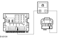
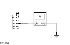
No REPAIR the circuit. TEST the system for normal operation. | | PINPOINT TEST H : THE CD CHANGER IS INOPERATIVE/DOES NOT OPERATE CORRECTLY | | TEST CONDITIONS | DETAILS/RESULTS/ACTIONS | | H1: CHECK THE CD CHANGER FOR VOLTAGE | | | 1 Disconnect CD changer C2ME27. | | | 2 Measure the voltage between the cd changer C2ME27 pin 1, circuit SBR05AWA (GY/RD), harness side and ground. | | | Is the voltage greater than 10 volts? Yes No REPAIR circuit SBR05AWA (GY/RD). TEST the system for normal operation. | | H2: CHECK THE CD CHANGER FOR GROUND | | | 1 Measure the resistance between the cd changer C2ME27 pin 6, circuit GD135M (BK/GY), harness side and ground. | | | Is the resistance less than 1 ohm? Yes No REPAIR circuit GD135M (BK/GY). TEST the system for normal operation. | | H3: CHECK THE CD CHANGER TO AUDIO UNIT CIRCUIT(S) FOR OPEN | | | 1 Disconnect Audio Unit C2ME03B. | | | 2 Measure the resistance between the following cd changer circuits and the audio unit circuit(s): - cd changer C2ME27 pin 3, circuit VME15B (GN/BK), harness side and audio unit C2ME03B pin 3, circuit VME15A (GN/BK), harness side.
- cd changer C2ME27 pin 8, circuit RME15B (VT/GY), harness side and audio unit C2ME03B pin 9, circuit RME15A (VT/GY), harness side.
- cd changer C2ME27 pin 4, circuit VME16B (GY/RD), harness side and audio unit C2ME03B pin 4, circuit RME16A (GY/RD), harness side.
- cd changer C2ME27 pin 9, circuit RME16B (YE/GY), harness side and audio unit C2ME03B pin 10, circuit RME16A (YE/GY), harness side.
| | | Are the resistances less than 1 ohm? Yes INSTALL a new cd changer. TEST the system for normal operation. If the concern persists, INSTALL a new audio unit.
REFER to: Audio Unit (415-01, Removal and Installation).
TEST the system for normal operation. No REPAIR the circuits as necessary. TEST the system for normal operation. If the concern persists, INSTALL a new audio unit.
REFER to: Audio Unit (415-01, Removal and Installation).
TEST the system for normal operation. | | PINPOINT TEST I : THE AUXILIARY INPUT DEVICE IS INOPERATIVE/DOES NOT OPERATE CORRECTLY | | TEST CONDITIONS | DETAILS/RESULTS/ACTIONS | | I1: CHECK THE OPERATION OF THE AUXILIARY INPUT DEVICE | | | 1 Operate the auxiliary input device outside of the vehicle. | | | Does the auxiliary input device operate outside of the vehicle? Yes No REFER to the auxiliary input device Owner Guide. | | I2: CHECK THE AUXILIARY INPUT DEVICE CONNECTOR | | | 1 Check the auxiliary input device connector for signs of damage or debris. | | | Is the auxiliary input device connector free of damage and debris? Yes No INSTALL a new auxiliary input device connector. TEST the system for normal operation. | | I3: CHECK CIRCUIT VME37A (BU/RD) FOR OPEN | | | 1 Disconnect Audio Unit C2ME03C. | | | 2 Disconnect Auxiliary Input Device C2ME37. | | | 3 Measure the resistance between the audio unit C2ME03C pin 5, circuit VME37A (BU/RD), harness side and auxiliary input device C2ME37 pin 4, circuit VME37A (BU/RD), harness side. | | | Is the resistance less than 1 ohm? Yes No REPAIR circuit VME37A (BU/RD). TEST the system for normal operation. | | I4: CHECK CIRCUIT VME38A (BN/RD) FOR OPEN | | | 1 Measure the resistance between the audio unit C2ME03C pin 11, circuit VME38A (BN/RD), harness side and auxiliary input device C2ME37 pin 1, circuit VME38A (BN/RD), harness side. | | | Is the resistance less than 1 ohm? Yes No REPAIR circuit VME38A (BN/RD). TEST the system for normal operation. | | I5: CHECK CIRCUIT DME37G (OG/GN) FOR GROUND | | | 1 Measure the resistance between the audio unit C2ME03C pin 6, circuit DME37G (OG/GN), harness side and ground. | | | Is the resistance less than 1 ohm? Yes INSTALL a new audio unit.
REFER to: Audio Unit (415-01, Removal and Installation).
TEST the system for normal operation. No REPAIR circuit DME37G (OG/GN). TEST the system for normal operation. | | PINPOINT TEST J : THE DIGITAL VERSATILE DISC (DVD) PLAYER IS INOPERATIVE/DOES NOT OPERATE CORRECTLY | | TEST CONDITIONS | DETAILS/RESULTS/ACTIONS | | J1: CHECK THE DVD PLAYER FOR POWER | | | 1 Disconnect DVD Player C2MR-A. | | | 2 Measure the voltage between the DVD player C2MR-A pin 4, circuit C_SBR05D (GY/RD), harness side and ground. | | | Is the voltage greater than 10 volts? Yes No REPAIR circuit C_SBR05D (GY/RD). TEST the system for normal operation. | | J2: CHECK THE DVD PLAYER FOR SWITCHED POWER | | | 1 Ignition switch in position II. | | | 2 Measure the voltage between the DVD player C2MR-A pin 7, circuit A_CBP04B (VT), harness side and ground. | | | Is the voltage greater than 10 volts? Yes No REPAIR circuit A_CBP04B (VT). TEST the system for normal operation. | | J3: CHECK THE DVD PLAYER FOR GROUND | | | 1 Ignition switch in position 0. | | | 2 Measure the resistance between the DVD player C2MR-A pin 8, circuit GD151L (BK/GN), harness side and ground. | | | Is the resistance less than 1 ohm? Yes No REPAIR circuit GD151L (BK/GN). TEST the system for normal operation. | | J4: CHECK THE DVD PLAYER ILLUMINATION CIRCUIT FOR POWER | | | 1 Turn the multi-function switch to the on position. | | | 2 Measure the voltage between the DVD player C2MR-A pin 6, circuit A_CLN17B (BN), harness side and ground. | | | Is the voltage greater than 10 volts? Yes INSTALL a new DVD player.
REFER to: Digital Versatile Disc (DVD) Player (415-01, Removal and Installation).
TEST the system for normal operation. No REPAIR circuit GLN17B (BN). TEST the system for normal operation. | | PINPOINT TEST K : THE VIDEO SYSTEM IS INOPERATIVE/DOES NOT OPERATE CORRECTLY | WARNING:Do not attempt to open or repair a video display as there are internal voltages in excess of 2000 volts. Failure to follow this instruction may result in personal injury. | | TEST CONDITIONS | DETAILS/RESULTS/ACTIONS | | K1: CHECK THE OPERATION OF THE VIDEO DISPLAY | | | 1 Change the head restraints/video displays between the two front seats. | | | Has the concern moved with the video display? Yes INSTALL a new head restraint/video display. TEST the system for normal operation. No For concern with the left-hand video display, GO to K2. For concern with the right-hand video display, GO to K18. | | K2: CHECK CIRCUITS CMR13B (WH/GN) AND CMR13A (WH/GN) FOR OPEN | | | 1 Disconnect DVD player C2MR-D. | | | 2 Disconnect Video display C33-T. | | | 3 Measure the resistance between the DVD player C2MR-D pin 1, circuit CMR13B (WH/GN), harness side and video display C33-T pin 3, circuit GMR13A (GN/WH), harness side. | | | Is the resistance less than 1 ohm? Yes No REPAIR circuit(s) GMR13B (WH/GN) or GMR13A (WH/GN). TEST the system for normal operation. | | K3: CHECK CIRCUITS LMR01B (BU/WH) AND LMR01A (BU/WH) FOR OPEN | | | 1 Measure the resistance between the DVD player C2MR-D pin 2, circuit LMR01B (BU/WH), harness side and video display C33-T pin 4, circuit LMR01A (BU/WH), harness side. | | | Is the resistance less than 1 ohm? Yes No REPAIR circuit(s) LMR01B (BU/WH) or LMR01A (BU/WH). TEST the system for normal operation. | | K4: CHECK CIRCUITS VMR10B (GY/OG) AND VMR10A (GY/OG) FOR OPEN | | | 1 Measure the resistance between the DVD player C2MR-D pin 3, circuit VMR10B (GY/OG), harness side and video display C33-T pin 5, circuit VMR10A (GY/OG), harness side. | | | Is the resistance less than 1 ohm? Yes No REPAIR circuit(s) VMR10B (GY/OG) or VMR10A (GY/OG). TEST the system for normal operation. | | K5: CHECK CIRCUITS VMR11B (VT/OG) AND VMR11A (VT/OG) FOR OPEN | | | 1 Measure the resistance between the DVD player C2MR-D pin 4, circuit VMR11B (VT/OG), harness side and video display C33-T pin 16, circuit VMR11A (VT/OG), harness side. | | | Is the resistance less than 1 ohm? Yes No REPAIR circuit(s) VMR11B (VT/OG) or VMR11A (VT/OG). TEST the system for normal operation. | | K6: CHECK CIRCUITS VMR12B (GY/VT) AND VMR12A (GY/VT) FOR OPEN | | | 1 Measure the resistance between the DVD player C2MR-D pin 5, circuit VMR12B (GY/VT), harness side and video display C33-T pin 11, circuit VMR11A (GY/VT), harness side. | | | Is the resistance less than 1 ohm? Yes No Repair circuit(s) VMR11B (GY/VT) or VMR11A (GY/VT). TEST the system for normal operation. | | K7: CHECK CIRCUITS RMR02B (BK/BU) AND RMR02A (BK/BU) FOR OPEN | | | 1 Measure the resistance between the DVD player C2MR-D pin 6, circuit RMR02B (BK/BU), harness side and video display C33-T pin 22, circuit RMR02A (BK/BU), harness side. | | | Is the resistance less than 1 ohm? Yes No REPAIR circuits RMR02B (BK/BU) or RMR02A (BK/BU). TEST the system for normal operation. | | K8: CHECK CIRCUITS VMR02B (GY/BK) AND VMR02A (GY/BK) FOR OPEN | | | 1 Measure the resistance between the DVD player C2MR-D pin 7, circuit VMR02B (GY/BK), harness side and video display C33-T pin 9, circuit VMR02A (GY/BK), harness side. | | | Is the resistance less than 1 ohm? Yes No REPAIR circuit(s) VMR02B (GY/BK) or VMR02A (GY/BK). TEST the system for normal operation. | | K9: CHECK CIRCUITS VMR03B (GY/VT) AND VMR03A (GY/VT) FOR OPEN | | | 1 Measure the resistance between the DVD player C2MR-D pin 8, circuit VMR03B (GY/VT), harness side and video display C33-T pin 20, circuit VMR03A (GY/VT), harness side. | | | Is the resistance less than 1 ohm? Yes No REPAIR circuit(s) VMR03B (GY/VT) or VMR03A (GY/VT). TEST the system for normal operation. | | K10: CHECK CIRCUITS VME05B (GY/WH) AND VME05A (GY/WH) FOR OPEN | | | 1 Measure the resistance between the DVD player C2MR-D pin 10, circuit VME05B (GY/WH), harness side and video display C33-T pin 10, circuit VME05A (GY/WH), harness side. | | | Is the resistance less than 1 ohm? Yes No REPAIR circuit(s) VME05B (GY/WH) or VME05A (GY/WH). TEST the system for normal operation. | | K11: CHECK CIRCUITS VMR04B (GY/OG) AND VMR04A (GY/OG) FOR OPEN | | | 1 Measure the resistance between the DVD player C2MR-D pin 11, circuit VMR04B (GY/OG), harness side and video display C33-T pin 21, circuit VMR04A (GY/OG), harness side. | | | Is the resistance less than 1 ohm? Yes No REPAIR circuit(s) VMR04B (GY/OG) or VMR04A (GY/OG). TEST the system for normal operation. | | K12: CHECK CIRCUITS RMR13E (BN/BU), RMR13B (BN/BU), RMR13A (BN/BU), RMR13C AND RMR13D FOR OPEN | | | 1 Measure the resistance between the following DVD player C2MR-D pins, harness side and video display C33-T pins, harness side. - C2MR-D pin 12, circuit RMR13E (BN/BU) and C33-T pin 14, circuit RMR13A (BN/BU).
- C2MR-D pin 12, circuit RMR13E (BN/BU) and C33-T pin 19, circuit RMR13D.
| | | Are the resistances less than 1 ohm? Yes No REPAIR circuit(s) RMR13E (BN/BU), RMR13B (BN/BU), RMR13A (BN/BU), RMR13C or RMR13D. TEST the system for normal operation. | | K13: CHECK CIRCUITS VMR09B (GN) AND VMR09A (GN) FOR OPEN | | | 1 Connect DVD Player C2MR-D. | | | 2 Disconnect DVD Player C2MR-B. | | | 3 Measure the resistance between the DVD player C2MR-B pin 1, circuit VMR09B (GN), harness side and video display C33-T pin 6, circuit VMR09A (GN), harness side. | | | Is the resistance less than 1 ohm? Yes No REPAIR circuit(s) VMR09B (GN) or VMR09A (GN). TEST the system for normal operation. | | K14: CHECK CIRCUITS DMR08B AND DMR08A FOR OPEN | | | 1 Measure the resistance between the DVD player C2MR-B pin 2, circuit DMR08B, harness side and video display C33-T pin 17, circuit DMR08A, harness side. | | | Is the resistance less than 1 ohm? Yes No REPAIR circuit(s) DMR08B or DMR08A. TEST the system for normal operation. | | K15: CHECK CIRCUITS VMR06B (BK/RD) AND VMR06A (BK/RD) FOR OPEN | | | 1 Measure the resistance between the DVD player C2MR-B pin 3, circuit VMR06B (BK/RD), harness side and video display C33-T pin 7, circuit VMR06A (BK/RD), harness side. | | | Is the resistance less than 1 ohm? Yes No REPAIR circuit(s) VMR06B (BK/RD) or VMR06A (BK/RD). TEST the system for normal operation. | | K16: CHECK CIRCUITS VMR07B (WH/BU) AND VMR07A (WH/BU) FOR OPEN | | | 1 Measure the resistance between the DVD player C2MR-B pin 4, circuit VMR07B (WH/BU), harness side and video display C33-T pin 18, circuit VMR07A (WH/BU), harness side. | | | Is the resistance less than 1 ohm? Yes No REPAIR circuit(s) VMR07B (WH/BU) or VMR07A (WH/BU). TEST the system for normal operation. | | K17: CHECK CIRCUITS DMR06B AND DMR06A FOR OPEN | | | 1 Measure the resistance between the DVD player C2MR-B pin 5, circuit DMR06B, harness side and video display C33-T pin 8, circuit DMR06A, harness side. | | | Is the resistance less than 1 ohm? Yes CHECK the DVD player. GO to Pinpoint Test J. No REPAIR circuit(s) DMR06B or DMR06A. TEST the system for normal operation. | | K18: CHECK CIRCUITS CMR27B (WH/OG) AND CMR27A (WH/OG) FOR OPEN | | | 1 Disconnect DVD Player C2MR-D. | | | 2 Disconnect Video Display C33-U. | | | 3 Measure the resistance between the DVD player C2MR-D pin 13, circuit CMR27B (WH/OG), harness side and video display C33-U pin 3, circuit CMR27A (WH/OG), harness side. | | | Is the resistance less than 1 ohm? Yes No REPAIR circuit(s) CMR27B (WH/OG) or CMR27A (WH/OG). TEST the system for normal operation. | | K19: CHECK CIRCUITS LMR15B (BU/OG) AND LMR15A (BU/OG) FOR OPEN | | | 1 Measure the resistance between the DVD player C2MR-D pin 14, circuit LMR15B (BU/OG), harness side and video display C33-U pin 4, circuit LMR15A (BU/OG), harness side. | | | Is the resistance less than 1 ohm? Yes No REPAIR circuit(s) LMR15B (BU/OG) or LMR15A (BU/OG). TEST the system for normal operation. | | K20: CHECK CIRCUITS VMR24B (GY/VT) AND VMR24A (GY/VT) FOR OPEN | | | 1 Measure the resistance between the DVD player C2MR-D pin 15, circuit VMR24B (GY/VT), harness side and video display C33-U pin 5, circuit VMR24A (GY/VT), harness side. | | | Is the resistance less than 1 ohm? Yes No REPAIR circuit(s) VMR24B (GY/VT) or VMR24A (GY/VT). TEST the system for normal operation. | | K21: CHECK CIRCUITS VMR25B (VT/GY) AND VMR25A (VT/GY) FOR OPEN | | | 1 Measure the resistance between the DVD player C2MR-D pin 16, circuit VMR25B (VT/GY), harness side and video display C33-U pin 16, circuit VMR25A (VT/GY), harness side. | | | Is the resistance less than 1 ohm? Yes No REPAIR circuit(s) VMR25B (VT/GY) or VMR25A (VT/GY). TEST the system for normal operation. | | K22: CHECK CIRCUITS VMR26B (YE/OG) AND VMR26A (YE/OG) FOR OPEN | | | 1 Measure the resistance between the DVD player C2MR-D pin 17, circuit VMR26B (YE/OG), harness side and video display C33-U pin 11, circuit VMR26A (YE/OG), harness side. | | | Is the resistance less than 1 ohm? Yes No REPAIR circuit(s) VMR26B (YE/OG) or VMR26A (YE/OG). TEST the system for normal operation. | | K23: CHECK CIRCUIT(S) RMR16B (BK/BU) AND RMR16A (BK/BU) FOR OPEN | | | 1 Measure the resistance between the DVD player C2MR-D pin 18, circuit RMR16B (BK/BU), harness side and video display C33-U pin 22, circuit RMR16A (BK/BU), harness side. | | | Is the resistance less than 1 ohm? Yes No REPAIR circuit(s) RMR16B (BK/BU) or RMR16A (BK/BU). TEST the system for normal operation. | | K24: CHECK CIRCUITS VMR16B (GY/BK) AND VMR16A (GY/BK) FOR OPEN | | | 1 Measure the resistance between the DVD player C2MR-D pin 19, circuit VMR16B (GY/BK), harness side and video display C33-U pin 9, circuit VMR16A (GY/BK), harness side. | | | Is the resistance less than 1 ohm? Yes No REPAIR circuit(s) VMR16B (GY/BK) or VMR16A (GY/BK). TEST the system for normal operation. | | K25: CHECK CIRCUITS VMR17B (VT/GN) AND VMR17A (VT/GN) FOR OPEN | | | 1 Measure the resistance between the DVD player C2MR-D pin 20, circuit VMR17B (VT/GN), harness side and video display C33-U pin 20, circuit VMR17A (VT/GN), harness side. | | | Is the resistance less than 1 ohm? Yes No REPAIR circuit(s) VMR17B (VT/GN) or VMR17A (VT/GN). TEST the system for normal operation. | | K26: CHECK CIRCUITS VMR19B (WH/VT) AND VMR19A (WH/VT) FOR OPEN | | | 1 Measure the resistance between the DVD player C2MR-D pin 22, circuit VMR19B (WH/VT), harness side and video display C33-U pin 10, circuit VMR19A (WH/VT), harness side. | | | Is the resistance less than 1 ohm? Yes No REPAIR circuit(s) VMR19B (WH/VT) or VMR19A (WH/VT). TEST the system for normal operation. | | K27: CHECK CIRCUITS VMR18B (YE/GN) AND VMR19A (YE/GN) FOR OPEN | | | 1 Measure the resistance between the DVD player C2MR-D pin 23, circuit VMR18B (YE/GN), harness side and video display C33-U pin 21, circuit VMR19A (YE/GN), harness side. | | | Is the resistance less than 1 ohm? Yes No REPAIR circuit(s) VMR18B (YE/GN) or VMR19A (YE/GN). TEST the system for normal operation. | | K28: CHECK CIRCUITS RMR27E (BN/VT), RMR27B (BN/VT), RMR27A (BN/VT), RMR27C AND RMR27D FOR OPEN | | | 1 Measure the resistance between the following DVD player C2MR-D pins, harness side and video display C33-U pins, harness side. - C2MR-D pin 24, circuit RMR27E (BN/VT) and C33-U pin 14, circuit RMR27A (BN/VT).
- C2MR-D pin 24, circuit RMR27E (BN/VT) and C33-U pin 19, circuit RMR27D.
| | | Are the resistances less than 1 ohm? Yes No REPAIR circuit(s) RMR27E (BN/VT), RMR27B (BN/VT), RMR27A (BN/VT), RMR27C or RMR27D. TEST the system for normal operation. | | K29: CHECK CIRCUITS VMR23B (GN/OG) AND VMR23A (GN/OG) FOR OPEN | | | 1 Connect DVD Player C2MR-D. | | | 2 Disconnect DVD Player C2MR-C. | | | 3 Measure the resistance between the DVD player C2MR-C pin 7, circuit VMR23B (GN/OG), harness side and video display C33-U pin 6, circuit VMR23A (GN/OG), harness side. | | | Is the resistance less than 1 ohm? Yes No REPAIR circuit(s) VMR23B (GN/OG) and VMR23A (GN/OG). TEST the system for normal operation. | | K30: CHECK CIRCUITS DMR22B AND DMR22A FOR OPEN | | | 1 Measure the resistance between the DVD player C2MR-C pin 21, circuit DMR22B, harness side and video display C33-U pin 17, circuit VMR24A (GY/VT), harness side. | | | Is the resistance less than 1 ohm? Yes No REPAIR circuit(s) DMR22B and DMR22A. TEST the system for normal operation. | | K31: CHECK CIRCUITS VMR20B (BN/WH) AND VMR20A (BN/WH) FOR OPEN | | | 1 Measure the resistance between the DVD player C2MR-C pin 4, circuit VMR20B (BN/WH), harness side and video display C33-U pin 7, circuit VMR20A (BN/WH), harness side. | | | Is the resistance less than 1 ohm? Yes No REPAIR the circuit. TEST the system for normal operation. | | K32: CHECK CIRCUITS VMR21B (BU/BN) AND VMR21A (BU/BN) FOR OPEN | | | 1 Measure the resistance between the DVD player C2MR-C pin 18, circuit VMR21B (BU/BN), harness side and video display C33-U pin 18, circuit VMR21A (BU/BN), harness side. | | | Is the resistance less than 1 ohm? Yes No REPAIR circuit(s) VMR21B (BU/BN) or VMR21A (BU/BN). TEST the system for normal operation. | | K33: CHECK CIRCUITS DMR20B AND DMR20A FOR OPEN | | | 1 Measure the resistance between the DVD player C2MR-C pin 19, circuit DMR20B, harness side and video display C33-U pin 8, circuit DMR20A, harness side. | | | Is the resistance less than 1 ohm? Yes CHECK the DVD player. GO to Pinpoint Test J. No REPAIR circuits DMR20B or DMR20A. TEST the system for normal operation. | |