| Diagnosis and Testing Refer to Wiring Diagrams Section 417-01, for schematic and connector information. Special Tool(s) | | Terminal Probe Kit 29-011A | General Equipment Digital Multimeter. Diagnostic tool. Inspection and Verification NOTE:The generic electronic module (GEM) is part of the central junction box (CJB). NOTE:If a new GEM module is being installed, the new module must be configured following installation. For this purpose, the vehicle-specific data is read out of the module to be changed using the diagnostic equipment and is transferred to the new module. REFER to: Modul-Konfiguration (418-01 Modul-Konfiguration, General Procedures), Zentralelektrikmodul (GEM) (419-10 Multifunktionsmodule, Diagnosis and Testing). NOTE:Before reading out the vehicle-specific data make sure that all electrical connections in the vehicle are reconnected so that the module and the diagnostic unit can communicate correctly. NOTE:Ensure correct engagement of the wiring harness connectors. - Verify the customer concern.
- Visually inspect for obvious signs of mechanical or electrical damage.
Visual Inspection Chart | Electrical systems | - Fuse(s)
- Bulb(s).
- Electrical connectors.
- Switch.
- Vehicle wiring harness.
| - If an obvious cause for an observed or reported concern is found, correct the cause (if possible) before proceeding to the next step. TEST the system for normal operation.
- If the concern persists after the visual inspection, PERFORM a fault diagnosis with the diagnostic unit and RECTIFY any displayed faults in accordance with the displayed fault description. TEST the system for normal operation.
- For vehicles with no stored fault(s), PROCEED in accordance with the symptom chart according to the fault symptom.
- After testing or rectifying the fault and after completion of operations, READ OUT the fault memories of all vehicle modules and DELETE any stored faults. READ OUT all fault memories again after a road test.
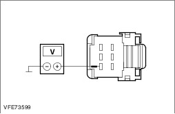
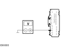
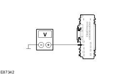
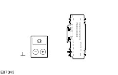
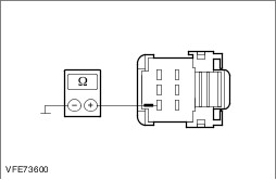
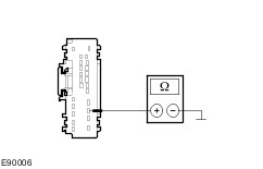
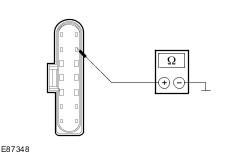
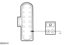
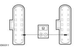
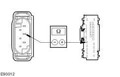
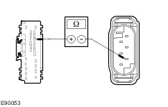
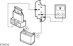
Trouble Code Table - Generic Electronic Module (GEM) | DTC | Description | Action | | 9D0613 | Circuit of left-hand turn signal lamps faulty. | REFER to: Blinkleuchten/seitliche Blinkleuchten/Warnblinkleuchten (417-01, Diagnosis and Testing). | | 9D0611 | Circuit of left-hand turn signal lamps faulty (short to ground). | REFER to: Blinkleuchten/seitliche Blinkleuchten/Warnblinkleuchten (417-01, Diagnosis and Testing). | | 91D311 | Circuit of left-hand side turn signal lamp faulty (short to ground). | REFER to: Blinkleuchten/seitliche Blinkleuchten/Warnblinkleuchten (417-01, Diagnosis and Testing). | | 91D313 | Circuit of left-hand side turn signal lamp faulty (open circuit). | REFER to: Blinkleuchten/seitliche Blinkleuchten/Warnblinkleuchten (417-01, Diagnosis and Testing). | | 9D0711 | Circuit of right-hand turn signal lamps faulty (short to ground). | REFER to: Blinkleuchten/seitliche Blinkleuchten/Warnblinkleuchten (417-01, Diagnosis and Testing). | | 9D0713 | Circuit of right-hand turn signal lamps faulty. | REFER to: Blinkleuchten/seitliche Blinkleuchten/Warnblinkleuchten (417-01, Diagnosis and Testing). | | 91CB11 | Circuit of right-hand side turn signal lamp faulty (short to ground). | REFER to: Blinkleuchten/seitliche Blinkleuchten/Warnblinkleuchten (417-01, Diagnosis and Testing). | | 91CB13 | Circuit of right-hand side turn signal lamp faulty (open circuit). | REFER to: Blinkleuchten/seitliche Blinkleuchten/Warnblinkleuchten (417-01, Diagnosis and Testing). | | 913C11 | Circuit of hazard warning switch illumination faulty (short to ground). | REFER to: Blinkleuchten/seitliche Blinkleuchten/Warnblinkleuchten (417-01, Diagnosis and Testing). | | 913C15 | Circuit of hazard warning switch illumination faulty (short to voltage or open circuit). | REFER to: Blinkleuchten/seitliche Blinkleuchten/Warnblinkleuchten (417-01, Diagnosis and Testing). | | 9D3524 | Circuit of hazard warning switch faulty. | REFER to: Blinkleuchten/seitliche Blinkleuchten/Warnblinkleuchten (417-01, Diagnosis and Testing). | | 913007 | Light switch unit, component fault. | REFER to: Scheinwerfer (417-01, Diagnosis and Testing). | | 9D0011 | Circuit of left-hand headlamp faulty (short to ground). | REFER to: Scheinwerfer (417-01, Diagnosis and Testing). | | 9D0111 | Circuit of right-hand headlamp faulty (short to ground). | REFER to: Scheinwerfer (417-01, Diagnosis and Testing). | | 9D0013 | Circuit of left-hand headlamp faulty (open circuit). | REFER to: Scheinwerfer (417-01, Diagnosis and Testing). | | 9D0113 | Circuit of right-hand headlamp faulty (open circuit). | REFER to: Scheinwerfer (417-01, Diagnosis and Testing). | | 909811 | Circuit of left-hand marker lamp (parking lamp) faulty (short to ground). | REFER to: Parkleuchten, Rückleuchten, Kennzeichenleuchten (417-01, Diagnosis and Testing). | | 909813 | Circuit of left-hand marker lamp (parking lamp) faulty (open circuit). | REFER to: Parkleuchten, Rückleuchten, Kennzeichenleuchten (417-01, Diagnosis and Testing). | | 909911 | Circuit of right-hand marker lamp (parking lamp) faulty (short to ground). | REFER to: Parkleuchten, Rückleuchten, Kennzeichenleuchten (417-01, Diagnosis and Testing). | | 909913 | Circuit of right-hand marker lamp (parking lamp) faulty (open circuit). | REFER to: Parkleuchten, Rückleuchten, Kennzeichenleuchten (417-01, Diagnosis and Testing). | | 909B13 | Circuit of license plate lamps faulty. | REFER to: Parkleuchten, Rückleuchten, Kennzeichenleuchten (417-01, Diagnosis and Testing). | | 909B11 | Circuit of license plate lamps faulty (short to ground). | REFER to: Parkleuchten, Rückleuchten, Kennzeichenleuchten (417-01, Diagnosis and Testing). | | 9A7913 | Circuit of rear fog lamps faulty. | REFER to: Nebelleuchten (417-01, Diagnosis and Testing). | | 9A7911 | Circuit of rear fog lamps faulty (short to ground). | REFER to: Nebelleuchten (417-01, Diagnosis and Testing). | | 402311. 402313 | Stop lamp circuit faulty. | REFER to: Bremsleuchten (417-01, Diagnosis and Testing). | | 911511 | Circuit of high-mounted stop lamp faulty (short to ground). | REFER to: Bremsleuchten (417-01, Diagnosis and Testing). | | 911513 | Circuit of high-mounted stop lamp faulty (open circuit). | REFER to: Bremsleuchten (417-01, Diagnosis and Testing). | | 90AD09 | Rain sensor/light sensor, component fault. | REFER to: automatisches Fahrlicht (417-01, Diagnosis and Testing), Scheibenwischer und Scheibenwaschanlage (501-16, Diagnosis and Testing). | | 90AD04 | Internal circuit of rain sensor/light sensor faulty. | REFER to: automatisches Fahrlicht (417-01, Diagnosis and Testing), Scheibenwischer und Scheibenwaschanlage (501-16, Diagnosis and Testing). | Symptom Chart Symptom Chart | Symptom | Possible Sources | Action | | The headlamp leveling is inoperative/does not operate correctly (vehicles with conventional headlamps). | * Fuse(s) * Circuit(s) * Lighting control module. * Adaptive front lighting module. * Headlamps * CJB | * | | The headlamp leveling is inoperative/does not operate correctly (vehicles with high intensity discharge headlamps). | * Fuse(s) * Circuit(s) * Headlamp leveling motor. * Gas discharge headlamps. * Headlamp leveling front sensor. * Headlamp leveling rear sensor. * Adaptive front lighting module. * CJB | * | Pinpoint Tests NOTE:Use a digital multimeter for all electrical measurements. | PINPOINT TEST A : THE HEADLAMP LEVELLING IS INOPERATIVE/DOES NOT OPERATE CORRECTLY (VEHICLES WITH CONVENTIONAL HEADLAMPS) | | TEST CONDITIONS | DETAILS/RESULTS/ACTIONS | | A1: DETERMINE THE CAUSE OF THE FAULT | | | 1 Ignition switch in position II. | | | 2 SWITCH ON dipped beams. | | | 3 ADJUST the headlamp levelling (UP/DOWN). | | | 4 CHECK the headlamp levelling. | | | Is the headlamp levelling left-hand side and right-hand side inoperative? Yes No - Left-hand headlamp levelling inoperative: GO to A18. - Right-hand headlamp levelling inoperative: GO to A21. | | A2: CHECK FUSE F43 (5 A) (EJB) | | | 1 Ignition switch in position 0. | | | 2 Disconnect fuse F43 (5 A) (EJB). | | | 3 CHECK fuse F43 (5 A) (EJB). | | | Is the fuse OK.? Yes No RENEW fuse F43 (5 A) (EJB). TEST the system for normal operation. If the fuse blows again, LOCATE and RECTIFY short using the Wiring Diagrams. TEST the system for normal operation. | | A3: CHECK THE VOLTAGE SUPPLY TO FUSE F43 (5 A) (EJB) | | | 1 Connect fuse F43 (5 A) (EJB). | | | 2 Ignition switch in position II. | | | 3 Measure the voltage between fuse F43 (5A) (EJB) and ground. | | | Does the meter display battery voltage? Yes No LOCATE AND RECTIFY the break in the voltage supply of fuse F43 (5 A) (EJB) using the Wiring Diagrams. TEST the system for normal operation. | | A4: CHECK FUSE F39 (15 A) (EJB) | | | 1 Ignition switch in position 0. | | | 2 Disconnect fuse F39 (15 A) (EJB). | | | 3 CHECK fuse F39 (15 A) (EJB). | | | Is the fuse OK.? Yes No RENEW fuse F39 (15 A) (EJB). TEST the system for normal operation. If the fuse blows again, LOCATE and RECTIFY short using the Wiring Diagrams. TEST the system for normal operation. | | A5: CHECK THE VOLTAGE SUPPLY TO FUSE F39 (15 A) (EJB) | | | 1 Connect fuse F39 (15 A) (EJB). | | | 2 Ignition switch in position II. | | | 3 Measure the voltage between fuse F39 (15 A) (EJB) and ground. | | | Does the meter display battery voltage? Yes No LOCATE AND RECTIFY the break in the voltage supply of fuse F39 (15 A) (EJB) using the Wiring Diagrams. TEST the system for normal operation. | | A6: CHECK THE COMMON VOLTAGE SUPPLY OF THE HEADLAMP LEVELLING MOTORS FOR OPEN CIRCUIT | | | 1 Ignition switch in position 0. | | | 2 Disconnect Left-hand headlamp from connector C1LF08. | | | 3 Ignition switch in position II. | | | 4 Measure the voltage between left-hand headlamp, connector C1LF08, pin 1, circuit CBB43B (GY), wiring harness side and ground. | | | Does the meter display battery voltage? Yes No LOCATE and RECTIFY the break in circuits between fuse F43 (5 A) (EJB) and soldered connection SP171 using the Wiring Diagrams. TEST the system for normal operation. | | A7: CHECK THE COMMON CONTROL CIRCUIT FOR HEADLAMP LEVELLING FOR SHORT TO BATTERY VOLTAGE | | | 1 Ignition switch in position 0. | | | 2 Disconnect Right-hand headlamp from connector C1LF09. | | | 3 Disconnect Lighting control module from connector C2LF23-C. | | | 4 Disconnect Adaptive front lighting module from connector C2LF23-A. | | | 5 Ignition switch in position II. | | | 6 Measure the voltage between adaptive front lighting module, connector C2LF23-D, pin 4, circuit A_VLF22A (VT/GN), wiring harness side and ground. | | | Does the meter display battery voltage? Yes LOCATE and RECTIFY the short to battery voltage in the circuits connected to the lighting control module, connector C2LF23-D, pin 4 using the Wiring Diagrams. TEST the system for normal operation. No | | A8: CHECK THE COMMON CONTROL CIRCUIT FOR HEADLAMP LEVELLING FOR SHORT TO BATTERY VOLTAGE | | | 1 Measure the voltage between adaptive front lighting module, connector C2LF23-C, pin 22, circuit VLF22E (VT/GN), wiring harness side and ground. | | | Does the meter display battery voltage? Yes LOCATE and RECTIFY the short to battery voltage in the circuits connected to the adaptive front lighting module, connector C2LF23-C, pin 22 using the Wiring Diagrams. TEST the system for normal operation. No | | A9: CHECK VOLTAGE SUPPLY TO ADAPTIVE FRONT LIGHTING MODULE FOR OPEN CIRCUIT | | | 1 Measure the voltage between adaptive front lighting module, connector C2LF23-C, pin 10, circuit CBB43C (GY), wiring harness side and ground. | | | Does the meter display battery voltage? Yes No LOCATE and RECTIFY break in circuit between soldered connection SP171 and adaptive front lighting module using the Wiring Diagrams. TEST the system for normal operation. | | A10: CHECK VOLTAGE SUPPLY TO ADAPTIVE FRONT LIGHTING MODULE FOR OPEN CIRCUIT | | | 1 Ignition switch in position 0. | | | 2 Disconnect Adaptive front lighting module from connector C2LF23-C. | | | 3 Ignition switch in position II. | | | 4 Measure the voltage between adaptive front lighting module, connector C2LF23-C, pin 9, circuit CBB39C (VT/WH), wiring harness side and ground. | | | Does the meter display battery voltage? Yes No LOCATE and RECTIFY the break in the circuit between fuse F39 (15A) (EJB) and the adaptive front lighting module using the Wiring Diagrams. TEST the system for normal operation. | | A11: CHECK GROUND CONNECTION TO ADAPTIVE FRONT LIGHTING MODULE FOR OPEN CIRCUIT | | | 1 Ignition switch in position 0. | | | 2 Measure the resistance between the adaptive front lighting module, connector C2LF23-C, pin 11, circuit GD138BU (BK/WH), wiring harness side and ground. | | | Is a resistance of less than 2 Ohms registered? Yes No LOCATE and RECTIFY break in circuit between adaptive front lighting module and ground connection G6D139 using the Wiring Diagrams. TEST the system for normal operation. | | A12: CHECK THE COMMON CONTROL CIRCUIT FOR HEADLAMP LEVELLING FOR SHORT TO GROUND | | | 1 Ignition switch in position 0. | | | 2 Measure the resistance between adaptive front lighting module, connector C2LF23-D, pin 4, circuit A_VLF22A (VT/GN), wiring harness side and ground. | | | Is a resistance of more than 10,000 Ohm measured? Yes No LOCATE and RECTIFY the short to ground in the circuits connected to the lighting control module, connector C2LF23-D, pin 4 using the Wiring Diagrams. TEST the system for normal operation. | | A13: CHECK THE COMMON CONTROL CIRCUIT FOR HEADLAMP LEVELLING FOR SHORT TO GROUND | | | 1 Measure the resistance between adaptive front lighting module, connector C2LF23-C, pin 22, circuit VLF22E (VT/GN), wiring harness side and ground. | | | Is a resistance of more than 10,000 Ohm measured? Yes No LOCATE and RECTIFY the short to ground in the circuits connected to the adaptive front lighting module, connector C2LF23-C, pin 22 using the Wiring Diagrams. TEST the system for normal operation. | | A14: CHECK COMMON CONTROL CIRCUIT OF HEADLAMP LEVELLING FOR OPEN CIRCUIT | | | 1 Measure the resistance between the lighting control module, connector C2LF23-D, pin 4, circuit A_VLF22A (VT/GN), wiring harness side and adaptive front lighting module, connector C2LF23-C, pin 19, circuit A_VLF22A (VT/GN), wiring harness side. | | | 2 Measure the resistance between adaptive front lighting module, connector C2LF23-C, pin 22, circuit VLF22E (VT/GN), wiring harness side and left-hand headlamp, connector C1LF08, pin 3, circuit VLF22A (VT/GN), wiring harness side. | | | Is a resistance of less than 2 Ohm measured in both cases? Yes No LOCATE and REPAIR the break in the affected circuit using the Wiring Diagrams. TEST the system for normal operation. | | A15: RULE OUT THE LEFT-HAND HEADLAMP AS A POSSIBLE CAUSE OF THE FAULT | | | 1 Connect Left-hand headlamp to connector C1LF08. | | | 2 Ignition switch in position II. | | | 3 Measure the voltage between adaptive front lighting module, connector C2LF23-C, pin 22, circuit VLF22E (VT/GN), wiring harness side and ground. | | | Does the meter display battery voltage? Yes RENEW left-hand headlamp. TEST the system for normal operation. No | | A16: RULE OUT THE RIGHT-HAND HEADLAMP AS A POSSIBLE CAUSE OF THE FAULT | | | 1 Ignition switch in position 0. | | | 2 Connect Right-hand headlamp to connector C1LF09. | | | 3 Ignition switch in position II. | | | 4 Measure the voltage between adaptive front lighting module, connector C2LF23-C, pin 22, circuit VLF22E (VT/GN), wiring harness side and ground. | | | Does the meter display battery voltage? Yes RENEW right-hand headlamp. TEST the system for normal operation. No | | A17: RULE OUT THE LIGHTS CONTROL MODULE AS THE CAUSE OF THE FAULT | | | 1 Ignition switch in position 0. | | | 2 Connect Lighting control module to connector C2LF23-D. | | | 3 Ignition switch in position II. | | | 4 SWITCH ON dipped beams. | | | 5 OPERATE the headlamp levelling (UP/DOWN). | | | 6 Measure the voltage between adaptive front lighting module, connector C2LF23-C, pin 19, circuit A_VLF22A (VT/GN), wiring harness side and ground. | | | Does the voltage measurement change in line with the headlamp levelling position. Yes RENEW the adaptive front lighting module. TEST the system for normal operation. No RENEW lighting control module. TEST the system for normal operation. | | A18: CHECK VOLTAGE SUPPLY OF LEFT-HAND HEADLAMP LEVELLING MOTOR FOR OPEN CIRCUIT | | | 1 Ignition switch in position 0. | | | 2 Disconnect Left-hand headlamp from connector C1LF08. | | | 3 Ignition switch in position II. | | | 4 SWITCH ON dipped beams. | | | 5 Measure the voltage between left-hand headlamp, connector C1LF08, pin 1, circuit CBB43B (GY), wiring harness side and ground. | | | Does the meter display battery voltage? Yes No LOCATE and RECTIFY the break in the circuit CBB43B (GY) between soldered connection SP171 and headlamp using the Wiring Diagrams. TEST the system for normal operation. | | A19: CHECK GROUND CONNECTION OF LEFT-HAND HEADLAMP LEVELLING MOTOR FOR OPEN CIRCUIT | | | 1 Ignition switch in position 0. | | | 2 Measure the resistance between the left-hand headlamp, connector C1LF08, pin 11, circuit GD130AE (BK/YE), wiring harness side and ground. | | | Is a resistance of less than 2 Ohms registered? Yes No LOCATE and RECTIFY the break in circuit GD130AE (BK/YE) between the headlamp and soldered connection SP371 using the Wiring Diagrams. TEST the system for normal operation. | | A20: CHECK CONTROL CIRCUIT OF LEFT-HAND HEADLAMP LEVELLING MOTOR FOR OPEN CIRCUIT | | | 1 Disconnect Right-hand headlamp from connector C1LF09. | | | 2 Measure the resistance between left-hand headlamp, connector C1LF08, pin 3, circuit VLF22A (VT/GN), wiring harness side and right-hand headlamp, connector C1LF09, pin 3, circuit VLF22C (VT/GN), wiring harness side. | | | Is a resistance of less than 2 Ohms registered? Yes RENEW left-hand headlamp. TEST the system for normal operation. No LOCATE and RECTIFY break in circuit between headlamp and intermediate connector C21A/B using the Wiring Diagrams. TEST the system for normal operation. | | A21: CHECK VOLTAGE SUPPLY OF RIGHT-HAND HEADLAMP LEVELLING MOTOR FOR OPEN CIRCUIT | | | 1 Ignition switch in position 0. | | | 2 Disconnect Right-hand headlamp from connector C1LF09. | | | 3 Ignition switch in position II. | | | 4 SWITCH ON dipped beams. | | | 5 Measure the voltage between right-hand headlamp, connector C1LF09, pin 1, circuit CBB43A (GY), wiring harness side and ground. | | | Does the meter display battery voltage? Yes No LOCATE and RECTIFY the break in the circuit CBB43A (GY) between soldered connection SP171 and headlamp using the Wiring Diagrams. TEST the system for normal operation. | | A22: CHECK GROUND CONNECTION OF RIGHT-HAND HEADLAMP LEVELLING MOTOR FOR OPEN CIRCUIT | | | 1 Ignition switch in position 0. | | | 2 Measure the resistance between the right-hand headlamp, connector C1LF09, pin 11, circuit GD132W (BK/VT), wiring harness side and ground. | | | Is a resistance of less than 2 Ohms registered? Yes No LOCATE and RECTIFY the break in circuit GD132W (BK/VT) between the headlamp and soldered connection SP380 using the Wiring Diagrams. TEST the system for normal operation. | | A23: CHECK CONTROL CIRCUIT OF RIGHT-HAND HEADLAMP LEVELLING MOTOR FOR OPEN CIRCUIT | | | 1 Disconnect Left-hand headlamp from connector C1LF08. | | | 2 Measure the resistance between left-hand headlamp, connector C1LF08, pin 3, circuit VLF22A (VT/GN), wiring harness side and right-hand headlamp, connector C1LF09, pin 3, circuit VLF22C (VT/GN), wiring harness side. | | | Is a resistance of less than 2 Ohms registered? Yes RENEW headlamp. TEST the system for normal operation. No LOCATE and RECTIFY break in circuit between headlamp and intermediate connector C21A/B using the Wiring Diagrams. TEST the system for normal operation. | | PINPOINT TEST B : THE HEADLAMP LEVELLING IS INOPERATIVE/DOES NOT OPERATE CORRECTLY (VEHICLES WITH XENON HEADLAMPS) | WARNING:High voltages of up to 30 kV are present in the system. Ensure that the headlamp assembly electrical connector is disconnected if the headlamp assembly is removed. | NOTE:It is not possible to adjust the headlamps manually. | NOTE:For testing the basic function of the automatic headlamp levelling system, switch on the dipped beams and change the load (rear axle) of the vehicle. Check if the headlamp levelling system adjusts the headlamps correctly. | NOTE:The headlamp levelling positioning motor cannot be replaced by itself. If necessary, it needs to be replaced together with the complete headlamp unit. | | TEST CONDITIONS | DETAILS/RESULTS/ACTIONS | | B1: DETERMINE THE CAUSE OF THE FAULT | | | 1 Ignition switch in position II. | | | 2 SWITCH ON dipped beams. | | | 3 CHECK the headlamp levelling. | | | Is the headlamp levelling left-hand side and right-hand side inoperative? Yes No - Left-hand headlamp levelling inoperative: GO to B25. - Right-hand headlamp levelling inoperative: GO to B28. | | B2: CHECK FUSE F43 (5 A) (EJB) | | | 1 Ignition switch in position 0. | | | 2 Disconnect fuse F43 (5 A) (EJB). | | | 3 CHECK fuse F43 (5 A) (EJB). | | | Is the fuse OK.? Yes No RENEW fuse F43 (5 A) (EJB). TEST the system for normal operation. If the fuse blows again, LOCATE and RECTIFY short using the Wiring Diagrams. TEST the system for normal operation. | | B3: CHECK THE VOLTAGE SUPPLY TO FUSE F43 (5 A) (EJB) | | | 1 Connect fuse F43 (5 A) (EJB). | | | 2 Ignition switch in position II. | | | 3 Measure the voltage between fuse F43 (5A) (EJB) and ground. | | | Does the meter display battery voltage? Yes No LOCATE AND RECTIFY the break in the voltage supply of fuse F43 (5 A) (EJB) using the Wiring Diagrams. TEST the system for normal operation. | | B4: CHECK FUSE F39 (15 A) (EJB) | | | 1 Ignition switch in position 0. | | | 2 Disconnect fuse F39 (15 A) (EJB). | | | 3 CHECK fuse F39 (15 A) (EJB). | | | Is the fuse OK.? Yes No RENEW fuse F39 (15 A) (EJB). TEST the system for normal operation. If the fuse blows again, LOCATE and RECTIFY short using the Wiring Diagrams. TEST the system for normal operation. | | B5: CHECK THE VOLTAGE SUPPLY TO FUSE F39 (15 A) (EJB) | | | 1 Connect fuse F39 (15 A) (EJB). | | | 2 Ignition switch in position II. | | | 3 Measure the voltage between fuse F39 (15 A) (EJB) and ground. | | | Does the meter display battery voltage? Yes No LOCATE AND RECTIFY the break in the voltage supply of fuse F39 (15 A) (EJB) using the Wiring Diagrams. TEST the system for normal operation. | | B6: CHECK THE COMMON VOLTAGE SUPPLY OF THE HEADLAMP LEVELLING MOTORS FOR OPEN CIRCUIT | | | 1 Ignition switch in position 0. | | | 2 Disconnect Left-hand headlamp from connector C1LF08. | | | 3 Ignition switch in position II. | | | 4 Measure the voltage between left-hand headlamp, connector C1LF08, pin 13, circuit CBB39E (VT/WH), wiring harness side and ground. | | | Does the meter display battery voltage? Yes No LOCATE and RECTIFY the break in circuit between fuse F39 (15 A) (EJB) and soldered connection SP172 using the Wiring Diagrams. TEST the system for normal operation. | | B7: CHECK VOLTAGE SUPPLY TO ADAPTIVE FRONT LIGHTING MODULE FOR OPEN CIRCUIT | | | 1 Ignition switch in position 0. | | | 2 Disconnect Adaptive front lighting module from connector C2LF23-C. | | | 3 Ignition switch in position II. | | | 4 Measure the voltage between adaptive front lighting module, connector C2LF23-C, pin 10, circuit CBB43C (GY), wiring harness side and ground. | | | Does the meter display battery voltage? Yes No LOCATE and RECTIFY break in circuit between soldered connection SP171 and adaptive front lighting module using the Wiring Diagrams. TEST the system for normal operation. | | B8: CHECK VOLTAGE SUPPLY TO ADAPTIVE FRONT LIGHTING MODULE FOR OPEN CIRCUIT | | | 1 Ignition switch in position 0. | | | 2 Disconnect Adaptive front lighting module from connector C2LF23-C. | | | 3 Ignition switch in position II. | | | 4 Measure the voltage between adaptive front lighting module, connector C2LF23-C, pin 9, circuit CBB39C (VT/WH), wiring harness side and ground. | | | Does the meter display battery voltage? Yes No LOCATE and RECTIFY the break in the circuit between fuse F39 (15A) (EJB) and the adaptive front lighting module using the Wiring Diagrams. TEST the system for normal operation. | | B9: CHECK GROUND CONNECTION TO ADAPTIVE FRONT LIGHTING MODULE FOR OPEN CIRCUIT | | | 1 Ignition switch in position 0. | | | 2 Measure the resistance between the adaptive front lighting module, connector C2LF23-C, pin 11, circuit GD138BU (BK/WH), wiring harness side and ground. | | | Is a resistance of less than 2 Ohms registered? Yes No LOCATE and RECTIFY break in circuit between adaptive front lighting module and ground connection G6D139 using the Wiring Diagrams. TEST the system for normal operation. | | B10: CHECK LIN DATABUS CONNECTION BETWEEN ADAPTIVE FRONT LIGHTING MODULE AND HEADLAMP LEVELLING MOTOR FOR SHORT CIRCUIT TO BATTERY VOLTAGE | | | 1 Ignition switch in position II. | | | 2 Measure the voltage between the adaptive front lighting module, connector C2LF23-C, pin 17, circuit VLF32B (YE), wiring harness side and ground. | | | Does the meter display battery voltage? Yes LOCATE and RECTIFY the short to battery voltage in circuits between adaptive front lighting module and headlamp levelling motor using the Wiring Diagrams. TEST the system for normal operation. No | | B11: CHECK LIN DATABUS CONNECTION BETWEEN ADAPTIVE FRONT LIGHTING MODULE AND HEADLAMP LEVELLING MOTOR FOR SHORT CIRCUIT TO GROUND | | | 1 Ignition switch in position 0. | | | 2 Measure the resistance between the adaptive front lighting module, connector C2LF23-C, pin 17, circuit VLF32B (YE), wiring harness side and ground. | | | Is a resistance of more than 10,000 Ohm measured? Yes No LOCATE and RECTIFY the short to ground in circuits between adaptive front lighting module and headlamp levelling motor using the Wiring Diagrams. TEST the system for normal operation. | | B12: CHECK LIN DATABUS CONNECTION BETWEEN ADAPTIVE FRONT LIGHTING MODULE AND HEADLAMP LEVELLING MOTOR FOR OPEN CIRCUIT | | | 1 Measure the resistance between adaptive front lighting module, connector C2LF23-C, pin 17, circuit VLF32B (YE), wiring harness side and left-hand headlamp levelling motor, connector C1LF08, pin 14, circuit VLF32A (YE), wiring harness side. | | | Is a resistance of less than 2 Ohms registered? Yes No LOCATE and RECTIFY break in circuit between adaptive front lighting module and intermediate connector C21A/B using the Wiring Diagrams. TEST the system for normal operation. | | B13: CHECK FRONT HEADLAMP LEVELLING SENSOR | | | 1 Disconnect Front headlamp levelling sensor from connector C5CD07. | | | 2 Check the front headlamp levelling sensor in accordance with the Component Checks in this operation. | | | Is the front headlamp levelling sensor OK? Yes No INSTALL a new front headlamp levelling sensor. TEST the system for normal operation. | | B14: CHECK REAR HEADLAMP LEVELLING SENSOR | | | 1 Disconnect Rear headlamp levelling sensor from connector C7CD12. | | | 2 Check the rear headlamp levelling sensor in accordance with the Component Checks in this operation. | | | Is the rear headlamp levelling sensor OK? Yes No INSTALL a new rear headlamp levelling sensor. TEST the system for normal operation. | | B15: CHECK THE VOLTAGE SUPPLY TO THE HEADLAMP LEVELLING SENSORS FOR OPEN CIRCUIT | | | 1 Connect Adaptive front lighting module to connector C2LF23-C. | | | 2 Connect Adaptive front lighting module to connector C2LF23-C. | | | 3 Ignition switch in position II. | | | 4 SWITCH ON dipped beams. | | | 5 Measure the voltage between front headlamp levelling sensor, connector C5CD07, pin 5, circuit LCD23B (GN/OG), wiring harness side and ground. | | | 6 Measure the voltage between rear headlamp levelling sensor, connector C7CD12, pin 5, circuit LCD23D (GN/OG), wiring harness side and ground. | | | Is a voltage of 5 Volts measured in both cases? Yes No - If no voltage is measured during both of the measurements: GO to B16. - Is a voltage of 5 Volts measured during just one measurement? LOCATE and RECTIFY break in the affected circuit between soldered connection SP406 and headlamp levelling sensor using the Wiring Diagrams. TEST the system for normal operation. | | B16: RULE OUT THE ADAPTIVE FRONT LIGHTING MODULE AS A POSSIBLE CAUSE OF THE FAULT | | | 1 Ignition switch in position 0. | | | 2 Disconnect Adaptive front lighting module from connector C2LF23-C. | | | 3 Measure the resistance between adaptive front lighting module, connector C2LF23-C, pin 8, circuit LCD23G (GN/OG), wiring harness side and front headlamp levelling sensor, connector C5CD07, pin 5, circuit LCD23B (GN/OG), wiring harness side. | | | Is a resistance of less than 2 Ohms registered? Yes RENEW the adaptive front lighting module. TEST the system for normal operation. No LOCATE and RECTIFY break in circuit between adaptive front lighting module and soldered connection SP406 using the Wiring Diagrams. TEST the system for normal operation. | | B17: RULE OUT THE ADAPTIVE FRONT LIGHTING MODULE AS A POSSIBLE CAUSE OF THE FAULT | | | 1 Ignition switch in position II. | | | 2 Measure the resistance between front headlamp levelling sensor, connector C5CD07, pin 1, circuit RCD02G (GN/BN), wiring harness side and ground. | | | 3 Measure the resistance between rear headlamp levelling sensor, connector C7CD12, pin 1, circuit RCD23D (WH/BN), wiring harness side and ground. | | | Is a resistance of less than 2 Ohm measured in both cases? Yes No - If a resistance of less than 2 Ohm is not measured in either measurement: RENEW the adaptive front lighting module. TEST the system for normal operation. - If a resistance of less than 2 Ohm is measured in one measurement: GO to B18. | | B18: RULE OUT THE ADAPTIVE FRONT LIGHTING MODULE AS A POSSIBLE CAUSE OF THE FAULT | | | 1 Ignition switch in position 0. | | | 2 Disconnect Adaptive front lighting module from connector C2LF23-C. | | | 3 Open circuit in ground connection to front headlamp levelling sensor: Measure the resistance between adaptive front lighting module, connector C2LF23-C, pin 14, circuit RCD02L (GN/BN), wiring harness side and front headlamp levelling sensor, connector C5CD07, pin 1, circuit RCD02G (GN/BN), wiring harness side. | | | 4 Open circuit in ground connection to rear headlamp levelling sensor: Measure the resistance between adaptive front lighting module, connector C2LF23-C, pin 15, circuit RCD23K (WH/BN), wiring harness side and rear headlamp levelling sensor, connector C7CD12, pin 1, circuit RCD23D (WH/BN), wiring harness side. | | | Is a resistance of less than 2 Ohms registered? Yes RENEW the adaptive front lighting module. TEST the system for normal operation. No LOCATE and RECTIFY break in circuit between adaptive front lighting module and headlamp levelling sensor using the Wiring Diagrams. TEST the system for normal operation. | | B19: CHECK SIGNAL CIRCUIT BETWEEN ADAPTIVE FRONT LIGHTING MODULE AND FRONT HEADLAMP LEVELLING SENSOR FOR SHORT CIRCUIT TO BATTERY VOLTAGE | | | 1 Ignition switch in position II. | | | 2 Measure the voltage between front headlamp levelling sensor, connector C5CD07, pin 4, circuit VCD10B (BN), wiring harness side and ground. | | | Does the meter display battery voltage? Yes LOCATE and RECTIFY the short to battery voltage in circuit(s) between adaptive front lighting module and headlamp levelling sensor using the Wiring Diagrams. TEST the system for normal operation. No | | B20: CHECK SIGNAL CIRCUIT BETWEEN ADAPTIVE FRONT LIGHTING MODULE AND FRONT HEADLAMP LEVELLING SENSOR FOR SHORT CIRCUIT TO GROUND | | | 1 Ignition switch in position 0. | | | 2 Measure the resistance between front headlamp levelling sensor, connector C5CD07, pin 4, circuit VCD10B (BN), wiring harness side and ground. | | | Is a resistance of more than 10,000 Ohm measured? Yes No LOCATE and RECTIFY the short to ground in circuit(s) between adaptive front lighting module and headlamp levelling sensor using the Wiring Diagrams. TEST the system for normal operation. | | B21: CHECK SIGNAL CIRCUIT BETWEEN ADAPTIVE FRONT LIGHTING MODULE AND FRONT HEADLAMP LEVELLING SENSOR FOR OPEN CIRCUIT | | | 1 Measure the resistance between the front headlamp levelling sensor, connector C5CD07, pin 4, circuit VCD10B (BN), wiring harness side and adaptive front lighting module, connector C2LF23-C, pin 20, circuit VCD10D (BN), wiring harness side. | | | Is a resistance of less than 2 Ohms registered? Yes No LOCATE and RECTIFY break in circuit(s) between adaptive front lighting module and headlamp levelling sensor using the Wiring Diagrams. TEST the system for normal operation. | | B22: CHECK SIGNAL CIRCUIT BETWEEN ADAPTIVE FRONT LIGHTING MODULE AND REAR HEADLAMP LEVELLING SENSOR FOR SHORT CIRCUIT TO BATTERY VOLTAGE | | | 1 Ignition switch in position II. | | | 2 Measure the voltage between rear headlamp levelling sensor, connector C7CD12, pin 4, circuit VCD12B (VT/WH), wiring harness side and ground. | | | Does the meter display battery voltage? Yes LOCATE and RECTIFY the short to battery voltage in circuit(s) between adaptive front lighting module and headlamp levelling sensor using the Wiring Diagrams. TEST the system for normal operation. No | | B23: CHECK SIGNAL CIRCUIT BETWEEN ADAPTIVE FRONT LIGHTING MODULE AND REAR HEADLAMP LEVELLING SENSOR FOR SHORT CIRCUIT TO GROUND | | | 1 Measure the resistance between rear headlamp levelling sensor, connector C7CD12, pin 4, circuit VCD12B (VT/WH), wiring harness side and ground. | | | Is a resistance of more than 10,000 Ohm measured? Yes No LOCATE and RECTIFY the short to ground in circuit(s) between adaptive front lighting module and headlamp levelling sensor using the Wiring Diagrams. TEST the system for normal operation. | | B24: CHECK SIGNAL CIRCUIT BETWEEN ADAPTIVE FRONT LIGHTING MODULE AND REAR HEADLAMP LEVELLING SENSOR FOR OPEN CIRCUIT | | | 1 Measure the resistance between the rear headlamp levelling sensor, connector C7CD12, pin 4, circuit VCD12B (VT/WH), wiring harness side and adaptive front lighting module, connector C2LF23-C, pin 16, circuit VCD12C (VT/WH), wiring harness side. | | | Is a resistance of less than 2 Ohms registered? Yes RENEW the adaptive front lighting module. TEST the system for normal operation. No LOCATE and RECTIFY break in circuit(s) between adaptive front lighting module and headlamp levelling sensor using the Wiring Diagrams. TEST the system for normal operation. | | B25: CHECK VOLTAGE SUPPLY OF LEFT-HAND HEADLAMP LEVELLING MOTOR FOR OPEN CIRCUIT | | | 1 Ignition switch in position 0. | | | 2 Disconnect Left-hand headlamp from connector C1LF08. | | | 3 Ignition switch in position II. | | | 4 SWITCH ON dipped beams. | | | 5 Measure the voltage between left-hand headlamp, connector C1LF08, pin 13, circuit CBB39E (VT/WH), wiring harness side and ground. | | | Does the meter display battery voltage? Yes No LOCATE and RECTIFY break in circuit between soldered connection SP172 and headlamp using the Wiring Diagrams. TEST the system for normal operation. | | B26: CHECK GROUND CONNECTION OF LEFT-HAND HEADLAMP LEVELLING MOTOR FOR OPEN CIRCUIT | | | 1 Ignition switch in position 0. | | | 2 Measure the resistance between the left-hand headlamp, connector C1LF08, pin 11, circuit GD130AE (BK/YE), wiring harness side and ground. | | | Is a resistance of less than 2 Ohms registered? Yes No LOCATE and RECTIFY the break in the circuit between the headlamp and soldered connection SP371 using the Wiring Diagrams. TEST the system for normal operation. | | B27: CHECK LIN DATABUS CONNECTION BETWEEN ADAPTIVE FRONT LIGHTING MODULE AND LEFT-HAND HEADLAMP FOR OPEN CIRCUIT | | | 1 Disconnect Right-hand headlamp from connector C1LF09. | | | 2 Measure resistance between left-hand headlamp, connector C1LF08, pin 14, circuit VLF32A (YE), wiring harness side and right-hand headlamp, connector C1LF09, pin 14, circuit VLF32C (YE), wiring harness side. | | | Is a resistance of less than 2 Ohms registered? Yes CHECK headlamp levelling motor. TEST the system for normal operation. If the concern persists, RENEW the headlamp. TEST the system for normal operation. No LOCATE and RECTIFY break in circuit between left-hand headlamp and intermediate connector C21A/B using the Wiring Diagrams. TEST the system for normal operation. | | B28: CHECK VOLTAGE SUPPLY OF RIGHT-HAND HEADLAMP LEVELLING MOTOR FOR OPEN CIRCUIT | | | 1 Ignition switch in position 0. | | | 2 Disconnect Right-hand headlamp from connector C1LF09. | | | 3 Ignition switch in position II. | | | 4 SWITCH ON dipped beams. | | | 5 Measure the voltage between right-hand headlamp, connector C1LF09, pin 13, circuit CBB39F (VT/WH), wiring harness side and ground. | | | Does the meter display battery voltage? Yes No LOCATE and RECTIFY break in circuit CBB39F (VT/WH) between soldered connection SP172 and headlamp using the Wiring Diagrams. TEST the system for normal operation. | | B29: CHECK GROUND CONNECTION OF RIGHT-HAND HEADLAMP LEVELLING MOTOR FOR OPEN CIRCUIT | | | 1 Ignition switch in position 0. | | | 2 Measure the resistance between the right-hand headlamp, connector C1LF09, pin 11, circuit GD132W (BK/VT), wiring harness side and ground. | | | Is a resistance of less than 2 Ohms registered? Yes No LOCATE and RECTIFY the break in circuit GD132W (BK/VT) between the headlamp and soldered connection SP380 using the Wiring Diagrams. TEST the system for normal operation. | | B30: CHECK THE LIN DATABUS CONNECTION FOR OPEN CIRCUIT | | | 1 Disconnect Left-hand headlamp from connector C1LF08. | | | 2 Measure resistance between left-hand headlamp, connector C1LF08, pin 14, circuit VLF32A (YE), wiring harness side and right-hand headlamp, connector C1LF09, pin 14, circuit VLF32C (YE), wiring harness side. | | | Is a resistance of less than 2 Ohms registered? Yes CHECK headlamp levelling motor. TEST the system for normal operation. If the concern persists, RENEW the headlamp. TEST the system for normal operation. No LOCATE and RECTIFY break in circuit between right-hand headlamp and intermediate connector C21A/B using the Wiring Diagrams. TEST the system for normal operation. | Component checks HEADLAMP LEVELLING SENSOR CAUTION:Electronic modules are sensitive to electrical charge. If exposed to these charges, damage may result. CAUTION:Be sure, that the headlamp levelling sensor is supplied with exactly 5 volts. NOTE:Check the headlamp levelling sensor when installed. - Switch off the ignition.
- Disconnect the electrical connector.
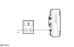
- Using an external 5 volts DC supply.
- Using a digital multimeter.
- Using a test cable, set up the test as in the following description.
- Check headlamp levelling sensor, front/rear.
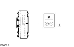
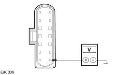
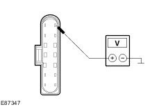
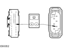
- Connect the positive terminal of the voltage supply with fused cable (5 A) to pin 5 of the headlamp levelling sensor and the negative terminal to pin 1.
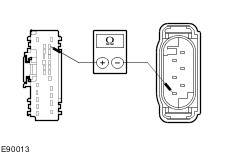
- To measure the voltage at the sensor, connect the positive terminal of the Digital Multimeter to pin 4 and the negative terminal to pin 1.
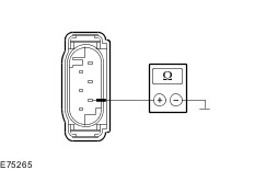
- Change the vehicle load during the measurement.
Measure the voltage. Is the range of values at the digital multimeter between 2.0 - 2.7 volts? If yes, the headlamp levelling sensor is OK. If no, RENEW the headlamp levelling sensor. |